forced mechanical locking gas spring
Patent No.:CN101487507 Date:2008-01-14
Google Patent: https://patents.google.com/patent/CN101487507A/en?oq=CN101487507
China Patent: http://epub.cnipa.gov.cn/
Abstract
This invention provides a type of forced mechanical locking gas spring, including a gas spring cylinder, a built-in piston inside the cylinder, a piston rod riveted to the piston, a guiding and sealing system, and a front connector attached to the piston rod, with a locking sleeve and a return spring attached to the front connector. The wrench bracket is welded onto the locking sleeve, and the strong locking wrench is installed on the wrench bracket. By adopting the two components of the wrench bracket and the strong locking wrench, it not only relies on the locking sleeve’s offset to support the lock but also has a strong locking wrench for forced locking, thereby doubling the safety factor during use. It is suitable for environments where malfunctions easily occur, such as facilities and equipment, and is also applicable in other fields such as sports equipment and treadmills.
Description
A Type of Forced Mechanical Locking Gas Spring
Technical Field The invention relates to a gas spring, specifically a type of forced mechanical locking gas spring.
Background Technology Gas springs are considered safety components abroad and have their own integrity requirements. In practical applications, there is an increasing focus on safety. In this context, using gas springs as mechanical locking devices has become more common. The current market’s locking devices rely solely on the offset of the locking sleeve to support the lock, which is unsuitable for environments prone to operational errors.
Summary of the Invention This invention provides a type of forced mechanical locking gas spring with double safety assurance.
To solve the above technical problems, the forced mechanical locking gas spring of this invention includes a gas spring cylinder, a built-in piston inside the cylinder, a piston rod riveted to the piston, a guiding and sealing system, and a front connector attached to the piston rod, with a locking sleeve and a return spring attached to the front connector. The wrench bracket is welded onto the locking sleeve, and the strong locking wrench is installed on the wrench bracket.
The strong locking wrench’s locking part is in the shape of an eccentric wheel and can be turned 180°.
The advantage of this structure is that it utilizes the two components of the wrench bracket and the strong locking wrench. It not only relies on the locking sleeve’s offset to support the lock but also has a strong locking wrench for forced locking, thus doubling the safety factor during use. It is suitable for environments where operational errors are likely, such as facilities and equipment, and is also applicable in other fields such as sports equipment and treadmills.
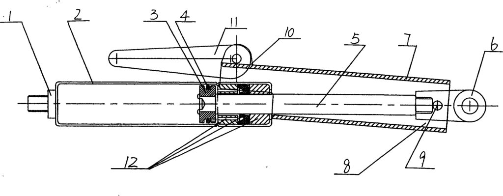
Description of the Drawings The figure is a schematic diagram of the structure of the invention.
Detailed Implementation As shown in the figure, the rear plug 1 and the cylinder 2 are welded into a sealed gas spring cylinder. The piston 3 and the O-ring 4 form a complete piston, with a guiding and sealing system 12 for guiding and sealing at this location. The piston is riveted to the piston rod 5. The front connector 6 is attached to the piston rod 5. The locking sleeve 7 and the return spring 8 are connected to the front connector 6 by the locking sleeve bolt 9. The wrench bracket 10 is welded onto the locking sleeve 7, and the strong locking wrench 11 is installed on the wrench bracket 10. The strong locking wrench 11’s locking part is shaped like an eccentric wheel and can be turned 180° to achieve the functions of strong locking and unlocking.
In operation, taking the maintenance of a large and heavy machine door as an example, the machine door needs to be opened and kept open for a long time during maintenance. At this time, the gas spring’s function is to open and support. The ordinary locking support component on the gas spring relies on the small force of the return spring 8 for the locking sleeve 7’s offset, achieving the purpose of support and locking, but it cannot prevent accidents. In this case, the wrench bracket 10 welded onto the locking sleeve 7 applies force to the strong locking wrench 11, which turns 180° like an eccentric wheel, initiating the strong lock function, thereby achieving dual mechanical locking and reducing safety risks.
Claims (2) – forced mechanical locking gas spring patent by LeiYan
- A Type of Forced Mechanical Locking Gas Spring, including a gas spring cylinder, a built-in piston inside the cylinder, a piston rod riveted to the piston, a guiding and sealing system, and a front connector attached to the piston rod with a locking sleeve and return spring attached to the front connector. It is characterized by: the wrench bracket being welded onto the locking sleeve, and the strong locking wrench being installed on the wrench bracket.
- According to claim 1, the strong locking wrench’s locking part is in the shape of an eccentric wheel and can be turned 180°.