Auto-Reset Lockable Gas Spring
Patent No.:CN201198885 Date:2008-04-28
Google Patent: https://patents.google.com/patent/CN201198885Y/en?oq=CN201198885
China Patent: http://epub.cnipa.gov.cn/
Abstract
This utility model provides an auto-reset lockable gas spring, composed of a cylinder, piston, and rear plug. The floating piston inside the cylinder divides it into two chambers, filled with nitrogen and hydraulic oil respectively. In the chamber filled with hydraulic oil, the piston is sealed with an O-ring. The piston is connected to a piston rod, valve core assembly, and valve needle. A wide groove is created on the piston, with the O-ring situated in the groove, and a reset hole is also made on the piston. This design incorporates a reset hole in the piston of the gas spring, and through the coordination of the piston, reset hole, and O-ring, it not only achieves automatic resetting but also enables a slow and steady extension and resetting function due to the internal pressure of the gas spring when external force is lost. This function is applicable to any type of lockable gas spring.
Description
A Type of Auto-Reset Lockable Gas Spring
Technical Field The utility model relates to a gas spring, specifically a gas spring that can automatically reset and be lockable.
Background Technology Currently, the market offers various types of lockable gas springs, but they are limited to the locking adjustment function and cannot achieve automatic resetting. With the widespread application of gas springs, devices such as bus seats, airplane cabin seats, and other single gas, gas-oil mixed, and gas-oil separated types of equipment can all be designed for automatic resetting to enhance convenience. However, there has not been an auto-reset lockable spring that can meet these needs.
Utility Model Content This utility model provides an auto-reset lockable gas spring.
To solve the above technical problems, this utility model provides an auto-reset lockable gas spring, which consists of a cylinder, a piston, and a rear plug. Inside the cylinder is a floating piston that divides the cylinder into two chambers filled with nitrogen and liquid oil, respectively. In the chamber filled with hydraulic oil, the piston is sealed with an O-ring. The piston is connected to a piston rod, valve core assembly, and valve needle. The characteristic of this design is that the piston has a wide groove with an O-ring in it and a reset hole on the piston.
The width of the groove on the piston is twice the diameter of the O-ring.
The reset hole consists of a vertical hole and a horizontal hole.
The horizontal hole of the reset hole is located at the centerline of the groove width on the piston.
Advantages of the Structure: The innovation of this structure lies in adding a reset hole to the piston, and through the coordination of the piston, reset hole, and O-ring, it achieves automatic resetting. In the absence of external force, due to the internal pressure of the gas spring, it can achieve a slow return of gas in both chambers, slowly extending and resetting. This function is applicable to any type of lockable gas spring.
Description of Drawings
Figure 1 is a schematic diagram of the structure of this utility model.
Figure 2 is an enlarged view of the piston of this utility model.
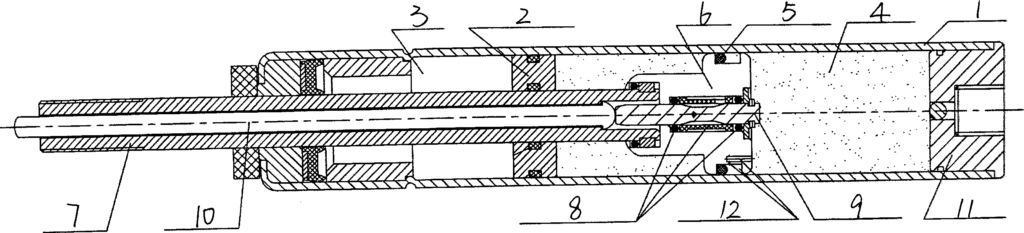
Detailed Implementation As shown in Figures 1 and 2, the bottom of the gas spring cylinder 1 is fixed with a rear plug 11, and inside it is a floating piston 2. The floating piston 2 divides the cylinder 1 into two chambers, filled with nitrogen 3 and liquid oil 4, respectively. In the chamber filled with hydraulic oil 4, the piston 6 is sealed with an O-ring 5. The piston 6 is connected to the valve core assembly 8, valve needle 9, piston rod 7, and the activation rod 10 on the piston rod 7. The main innovation of this structure lies in increasing the width of the groove 15 on the piston 6 to twice the diameter of the O-ring 5 and adding a reset hole 12 on the piston 6. The reset hole 12 consists of a vertical hole 13 and a horizontal hole 14, with the horizontal hole 14 located at the centerline of the groove width on the piston 6. The O-ring 5 moves up and down within the wide groove 15 on the piston 6 along the horizontal hole 14 of the reset hole 12, sealing as the lockable gas spring is compressed and extended. When the lockable gas spring is in a compressed state, the O-ring 5 floats to the upper end of the horizontal hole 14 of the reset hole 12 for sealing. During the extension adjustment, the O-ring 5 floats to the lower end of the horizontal hole 14 of the reset hole 12 for sealing. The compression and extension adjustment of this spring are the same as other lockable gas springs. The difference is that in the absence of external force, due to the internal pressure of the lockable gas spring, the O-ring 5 also floats to the lower end of the horizontal hole 14 of the reset hole 12, thus achieving the function of slowly returning gas in both chambers and slowly extending and resetting. This function is suitable for any type of lockable gas spring, including single gas, gas-oil mixed, gas-oil separated (including front separation and rear separation) types.
Claims (4) – Auto-Reset Lockable Gas Spring invented by LeiYan Gas Springs
- A Type of Auto-Reset Lockable Gas Spring, consisting of a cylinder, piston, and rear plug, with a floating piston built inside the cylinder. The floating piston divides the cylinder into two chambers filled with nitrogen and liquid oil respectively. In the chamber filled with hydraulic oil, the piston is sealed with an O-ring. The piston is connected to a piston rod, valve core assembly, and valve needle. It is characterized by: a wide groove on the piston, with the O-ring situated in the groove, and a reset hole on the piston.
- According to claim 1, the width of the groove on the piston is twice the diameter of the O-ring.
- According to claim 1, the reset hole consists of a vertical hole and a horizontal hole.
- According to claim 3, the horizontal hole of the reset hole is located at the centerline of the groove width on the piston.