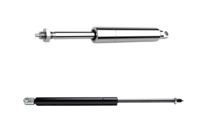
Annex A – Gas Spring Design Calculation
Annex A (normative) Design of the minimum extension force F1 A.1 Minimum extension force F1 of compression gas spring The minimum extension force F1 of a compression gas spring can be calculated according to formula (A.1), while the schematic diagram for the calculation of minimum extension force is shown in Figure A.1.Read More…
Design calculation of gas spring cylinder
7.5 Design calculation of gas spring cylinder 7.5.1 Calculation of cylinder inner diameter The cylinder inner diameter of the gas spring should be decided according to GB/T 2348, and it is recommended to adopt the ratio of the cylinder inner diameter D1 to the piston rod diameter d as approximate D1/d = 2,Read More…
Stroke S, extended length L and piston rod of gas spring calculation
7.3 Stroke S and extended length L 7.3.1 Schematic diagram of the overall dimensions of gas spring See Figure 11 to Figure 14 for the basic dimensions (stroke S, extended length L, etc.) of common gas springs, including compression gas spring, lockable gas spring, chair height adjustment gas spring and stretchingRead More…
calculation of gas spring
7 Design calculation 7.1 Overview The design calculation for a gas spring generally involves: force, force ratio, stroke and extended length, piston rod diameter, cylinder inner diameter and wall thickness. The design calculation for the gas spring is based on an ambient temperature of 20°C ± 2°C, and the influenceRead More…
Gas Spring Design calculation principle
6 Gas Spring Design calculation principle At constant ambient temperature, the working process of the gas spring can be regarded as an isothermal process, which should follow the gas state formula of Boyle’s law; see formula (1) or formula (2): PV=C………………(1) Or P1V1=P2V2 ………………(2) where P is the pressure (the pressure insideRead More…


