Tag: A Pneumatic Seat Angle Reset Device
A Pneumatic Seat Angle Reset Device
Patent No.:CN201468593U Date:2009-06-15
Google Patent: https://patents.google.com/patent/CN201468593U/en?oq=CN201468593U
China Patent: http://epub.cnipa.gov.cn/
A Pneumatic Seat Angle Reset Device
Abstract
This utility model relates to a reset device, particularly a pneumatic seat angle reset device. The technical problem to be solved is to provide a pneumatic seat angle reset device with low operating noise and flexible resetting. It includes a movable cylinder, a rear plug, a reset sleeve assembly, a piston rod, and an outer sleeve. The movable cylinder is fitted with an outer sleeve, with one end welded to the rear plug. The inner chamber contains a reset sleeve assembly, which connects to the outer sleeve’s end through a piston rod. The movable cylinder contains a thrust piston connected to one end of the reset sleeve assembly. The space between the thrust piston and the rear plug is filled with gas. This design ensures silent resetting, flexible rotation, and extended service life due to the O-ring on the thrust piston ensuring gas sealing performance.
Description
A Pneumatic Seat Angle Reset Device
Technical Field This utility model relates to a reset device, specifically a pneumatic seat angle reset device.
Background Technology Traditional seat reset devices use mechanical springs and end face bearings to reset seats. These devices are prone to making noise, lack flexibility, and are difficult to assemble.
Utility Model Content The technical problem to be solved is to provide a pneumatic seat angle reset device with low operating noise and flexible resetting.
To solve the above technical problems, the utility model provides a pneumatic seat angle reset device, which includes a movable cylinder, a rear plug, a reset sleeve assembly, a piston rod, and an outer sleeve. The movable cylinder is fitted with an outer sleeve, with one end welded to the rear plug. The inner chamber contains a reset sleeve assembly, which connects to the outer sleeve’s end through a piston rod. The innovation lies in the movable cylinder containing a thrust piston connected to one end of the reset sleeve assembly, with gas filling the space between the thrust piston and the rear plug as the reset power.
Further, balls are installed between the thrust piston and the reset sleeve assembly.
Further, the gas can be nitrogen or argon.
Further, the thrust piston is connected with an O-ring.
Advantages of the Utility Model The use of gas and balls ensures silent and flexible resetting, with the combination of the thrust piston and the O-ring ensuring the sealing performance of the nitrogen gas and extending the service life.
Description of Drawings
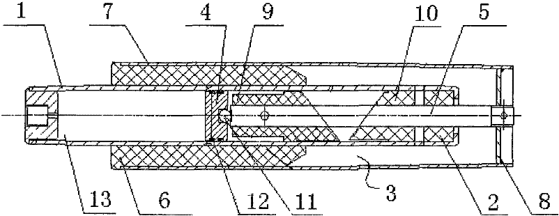
The figure is a schematic diagram of the pneumatic seat angle reset device.
Detailed Implementation As shown in the figure, it includes an outer sleeve 7, a guide sleeve 6, a bottom pad 8, a movable cylinder 1, a rear plug 2, a reset sleeve assembly 3, a piston rod 5, a thrust piston 4, balls 11, and an O-ring 12.
The front end of the outer sleeve 7 is fixedly connected to the guide sleeve 6, and the end is welded to the bottom pad 8. The outer sleeve 7 is also connected to the movable cylinder 1, which slides up and down guided by the guide sleeve 6.
The top end of the movable cylinder 1 is connected to the rear plug 2. The inner chamber contains a reset sleeve assembly 3 for resetting the seat angle. The reset sleeve assembly 3 consists of a conical movable reset sleeve 9 and a fixed reset sleeve 10, which are similar in structure. The fixed reset sleeve 10 is fixed at the end of the movable cylinder 1, and one end of the movable reset sleeve 9 is connected to the piston rod 5. The piston rod 5 passes through the fixed reset sleeve 10 and connects to the bottom pad 8 of the outer sleeve 7. The piston rod 5 and the fixed reset sleeve 10 have a sliding fit.
To ensure silent resetting, a thrust piston 4 is connected inside the movable cylinder 1, with gas 13 filling the space between the thrust piston 4 and the rear plug 2 as the reset power. During use, the movable cylinder 1 and the fixed reset sleeve 10 move downward under external force, separating the conical surfaces of the movable reset sleeve 9 and the fixed reset sleeve 10. Simultaneously, the thrust piston 4 compresses the gas 13 in the sealed movable cylinder 1. When the external force is removed, the compressed gas 13 is released, pushing the movable cylinder 1 upward. The conical surfaces of the movable reset sleeve 9 and the fixed reset sleeve 10 slide relative to each other until they overlap, completing the seat’s rotational reset silently. The gas 13 can be nitrogen, argon, or other inert gases.
To ensure more flexible and silent resetting, balls 11 are connected between the thrust piston 4 and the movable reset sleeve 9, concentrating the thrust point and minimizing resistance during rotation. Additionally, an O-ring 12 is connected between the outer circumference of the thrust piston 4 and the movable cylinder 1, enhancing the sealing performance of the movable cylinder 1 and extending the service life of the pneumatic seat angle reset device.
Claims (4) – A Pneumatic Seat Angle Reset Device, invented by LeiYan Gas Spring, a pioneer Chinese Gas Spring Manufacturer
According to claim 1, characterized by: the thrust piston is connected with an O-ring.
A pneumatic seat angle reset device, including a movable cylinder, a rear plug, a reset sleeve assembly, a piston rod, and an outer sleeve. The movable cylinder is fitted with an outer sleeve, with one end welded to the rear plug. The inner chamber contains a reset sleeve assembly, which connects to the outer sleeve’s end through a piston rod. It is characterized by: the movable cylinder contains a thrust piston connected to one end of the reset sleeve assembly, with gas filling the space between the thrust piston and the rear plug.
According to claim 1, characterized by: balls are installed between the thrust piston and the reset sleeve assembly.
According to claim 1, characterized by: the gas can be nitrogen or argon.