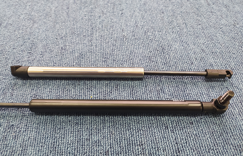
Tag: dynamic damping gas spring
A Dual Sealing Structure Gas Spring with simultaneous Inflation and Sealing
Patent No.:CN206268354U Date:2016-08-11
Google Patent: https://patents.google.com/patent/CN206268354U/en?oq=CN206268354U
China Patent: http://epub.cnipa.gov.cn/
Abstract
This utility model relates to a gas spring with Dual Sealing Structure Gas Spring with simultaneous Inflation and Sealing. It includes a cylinder, a rear plug installed in the left end of the cylinder’s inner hole, and at least one set of sealing rings installed between the outer wall of the rear plug and the inner wall of the cylinder. The piston structure of this utility model is reasonable and operates stably, ensuring precise and consistent inflation force, improving the sealing performance and service life of the guiding sealing assembly.
Description
A Dual Sealing Structure Gas Spring with simultaneous Inflation and Sealing
Technical Field This utility model relates to A Dual Sealing Structure Gas Spring with simultaneous Inflation and Sealing.
Background Technology Currently, the gas spring described in “CN201120169308.0 – Repairable Gas Spring” cannot achieve direct empty cylinder inflation, resulting in inaccurate inflation amounts and subsequent gas or oil leakage. Existing gas springs typically use a sealing guide section with a welded rear plug after inflation, resulting in a short lifespan for the sealing rings.
Utility Model Content The technical problem this utility model aims to solve is to provide A Dual Sealing Structure Gas Spring with simultaneous Inflation and Sealing that is reasonably designed, compact in structure, and convenient to use.
To solve the above problems, the technical solution adopted in this utility model is as follows: A Dual Sealing Structure Gas Spring with simultaneous Inflation and Sealing, including a cylinder, a rear plug installed in the left end of the cylinder’s inner hole, and at least one set of sealing rings installed between the outer wall of the rear plug and the inner wall of the cylinder.
Further improvements:
- At least one annular groove for placing the sealing ring is set on the outer wall of the rear plug.
- A sealing groove is set on the rear plug, and a left sealing end is set at the left end of the cylinder, hooking into the sealing groove.
- A piston rod is installed inside the cylinder, and a guiding sealing assembly is set at the right end of the cylinder, including sequentially installed first lip seal, middle seal spacer, and second lip seal guiding sleeve from left to right within the cylinder. A buffer pressure-free sealing area is formed between the first lip seal and the middle seal spacer, and between the middle seal spacer and the second lip seal guiding sleeve.
- The right end of the cylinder is set with a right sealing end. The second sealing guiding sleeve has a right sealing annular groove, hooking into the right sealing annular groove.
- The outer side wall of the middle seal spacer is press-fitted with the inner side wall of the cylinder.
- A piston rod is installed inside the cylinder, with a piston and piston plate set on the piston rod, dividing the cylinder chamber into a rod chamber on the right and a non-rod chamber on the left. The piston and piston plate are tightly riveted on the piston rod. A fitting gap is set between the inner side wall of the cylinder and the outer side wall of the piston. A sealing groove is set between the right side of the piston and the left side of the piston plate. Damping holes and O-rings are set on the piston, and ventilation grooves are set on the piston plate.
- The ventilation grooves are centripetal grooves, dividing the piston plate into three or more odd or even blades.
- The ventilation grooves can be centripetal arcs or long curves.
- A left connecting piece is installed at the left end of the rear plug, and a right connecting piece is installed at the right end of the piston rod.
Advantages:
- The piston structure of this utility model is reasonable and operates stably.
- Ventilation grooves divide the piston plate into helical blade structures, improving rigidity and ensuring stable ventilation.
- This utility model adopts post-inflation sealing and riveting. Additional O-rings are added to the rear plug. When the rear plug and cylinder are separated, the inner cavity of the empty cylinder is high-pressure sealed and inflated, ensuring consistent inflation volume and accurate gas spring force values. Immediately after cylinder inflation, the sealing mold of the high-pressure inflation device, i.e., the left and right sealing molds, push the rear plug into the cylinder and simultaneously seal it.
- The piston plate is a new five-pointed daisy piston plate. The five points of the daisy piston improve the concentricity of the piston rod, guiding sealing assembly, cylinder, piston, and piston plate, ensuring more stable operation of the gas spring.
- The guiding sealing assembly adopts secondary pressure-free sealing. Pressure-free sealing means there is initially no pressure between the first seal and the second seal due to simultaneous inflation and sealing. The first seal blocks the pressure, and the second seal, not being pressurized, creates negligible friction on the piston rod. As the gas spring operates, the surface of the piston rod accumulates a reasonable oil film, gradually pressurizing the second seal, thus improving the sealing performance and lifespan of the guiding sealing assembly.
- This structural form can be widely applied to any type of gas spring.
Description of Drawings
- Figure 1: Schematic diagram of the gas spring structure with the rear plug to be assembled.
- Figure 2: Partial schematic diagram of the left side of the assembled gas spring.
- Figure 3: Schematic diagram of the piston plate structure.
- Figure 4: Right view schematic diagram of the piston plate structure.
- Figure 5: Schematic diagram of the gas spring assembly equipment.
- Figure 6: Schematic diagram of the inflation gas circuit.
- Figure 7: Schematic diagram of the sealing oil circuit.
- Figure 8: Schematic diagram of the clamping scheme 1 oil circuit.
- Figure 9: Schematic diagram of the clamping scheme 2 gas circuit.
Components:
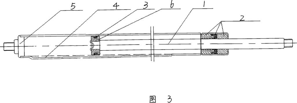
1.Cylinder
2.Piston rod
3.Right connecting piece
4.Left connecting piece
5.Rear plug
6.Sealing ring
7.Piston
8.Damping hole
9.Sealing groove
10.Piston plate
11.First lip seal
12.Fitting gap
13.Ventilation groove
14.Middle seal spacer
15.Second lip seal guiding sleeve
16.Left sealing end
17.Sealing groove
101.Gas spring to be assembled
102.Base
103.Lowering cylinder or hydraulic cylinder
104.Movable lowering seat
105.Upper half-round replaceable frame
106.Lower half-round replaceable frame
107.Left push-in hydraulic cylinder
108.Replaceable left push-in inflation seat
110.Inflation channel
111.End face sealing ring
112.Left sealing mold
113.Inflation sealing face
114.Right push-in sealing hydraulic cylinder
115.Right sealing mold
116.High-pressure inflation pump
117.Two-position three-way solenoid valve
118.Electronic pressure gauge
119.Sealing oil pump
120.Sealing push-in two-position four-way solenoid valve
121.Clamping oil pump
122.Clamping three-position four-way solenoid valve
123.Balancing circuit
124.Oil replenishing check valve
Detailed Implementation As shown in Figures 1-4, this embodiment of A Dual Sealing Structure Gas Spring with simultaneous Inflation and Sealing includes a cylinder 1, a rear plug 5 installed in the left end of the cylinder 1’s inner hole, and at least one set of sealing rings 6 installed between the outer wall of the rear plug 5 and the inner wall of the cylinder 1.
At least one annular groove for placing the sealing ring 6 is set on the outer wall of the rear plug 5. A sealing groove 17 is set on the rear plug 5, with a left sealing end 16 at the left end of the cylinder 1, hooking into the sealing groove 17.
A piston rod 2 is installed inside the cylinder 1, with a guiding sealing assembly set at the right end of the cylinder 1, including sequentially installed first lip seal 11, middle seal spacer 14, and second lip seal guiding sleeve 15 from left to right within the cylinder 1. A buffer pressure-free sealing area is formed between the first lip seal 11 and the middle seal spacer 14, and between the middle seal spacer 14 and the second lip seal guiding sleeve 15.
The right end of the cylinder 1 is set with a right sealing end. The second sealing guiding sleeve 15 has a right sealing annular groove, hooking into the right sealing annular groove.
The outer side wall of the middle seal spacer 14 is press-fitted with the inner side wall of the cylinder 1.
A piston rod 2 is installed inside the cylinder 1, with a piston 7 and piston plate 10 set on the piston rod 2. The piston 7 divides the cylinder 1 chamber into a rod chamber on the right and a non-rod chamber on the left. The piston 7 and piston plate 10 are tightly riveted on the piston rod 2. A fitting gap 12 is set between the inner side wall of the cylinder 1 and the outer side wall of the piston 7. A sealing groove 9 is set between the right side of the piston 7 and the left side of the piston plate 10. Damping holes 8 and O-rings are set on the piston 7, and ventilation grooves 13 are set on the piston plate 10.
The ventilation grooves 13 are centripetal grooves, dividing the piston plate 10 into three or more odd or even blades. The ventilation grooves 13 can be centripetal arcs or long curves.
A left connecting piece 4 is installed at the left end of the rear plug 5, and a right connecting piece 3 is installed at the right end of the piston rod 2.
The preferred annular groove for placing the sealing ring 6 is two, with one sealing ring 6 installed in each groove. This structure is reasonable and provides good sealing effect.
The right sealing end hooks into the right sealing annular groove. The sealing groove 17 and left sealing end 16 hook together, making assembly convenient, free of welding deformation, precise, reasonable in structure, and long-lasting.
The guiding sealing assembly includes sequentially installed first lip seal 11, middle seal spacer 14, and second lip seal guiding sleeve 15 within the cylinder 1 from left to right, ensuring a reasonable structure and long life.
The outer side wall of the middle seal spacer 14 is press-fitted firmly with the inner side wall of the cylinder 1.
The piston structure of this utility model is reasonable and operates stably.
The ventilation grooves 13 divide the piston plate 10 into helical blade structures, improving rigidity and ensuring stable ventilation.
This utility model adopts post-inflation sealing and riveting. Additional O-rings are added to the rear plug 5. When the rear plug 5 and cylinder 1 are separated, the inner cavity of the empty cylinder 1 is high-pressure sealed and inflated, ensuring consistent inflation volume and accurate gas spring force values. Immediately after cylinder inflation, the sealing mold of the high-pressure inflation device, i.e., the left and right sealing molds 112 and 115, push the rear plug 5 into the cylinder 1 and simultaneously seal it.
The piston plate 10 is a new five-pointed daisy piston plate. The five points of the daisy piston improve the concentricity of the piston rod 2, guiding sealing assembly, cylinder 1, piston 7, and piston plate 10, ensuring more stable operation of the gas spring.
The guiding sealing assembly adopts secondary pressure-free sealing. Pressure-free sealing means there is initially no pressure between the first and second seals due to simultaneous inflation and sealing. The first seal blocks the pressure, and the second seal, not being pressurized, creates negligible friction on the piston rod. As the gas spring operates, the surface of the piston rod accumulates a reasonable oil film, gradually pressurizing the second seal, thus improving the sealing performance and lifespan of the guiding sealing assembly.
This structural form can be widely applied to any type of gas spring.
As shown in Figures 5-9, the equipment for assembling A Dual Sealing Structure Gas Spring with simultaneous Inflation and Sealing includes a base 102, a clamping device set in the middle of the base 102, and an inflation sealing device set on the left side of the base 102.
The clamping device includes a vertical lowering cylinder or hydraulic cylinder 103 installed above the middle of the base 102, a movable lowering seat 104 installed at the lower end of the lowering cylinder or hydraulic cylinder 103, an upper half-round replaceable frame 105 set at the lower end of the movable lowering seat 104, and a lower half-round replaceable frame 106 installed on the base 102.
The lower half-round replaceable frame 106 and upper half-round replaceable frame 105 clamp the horizontally set gas spring 101 to be assembled.
The inflation sealing device includes a left push-in hydraulic cylinder 107 installed at the left end of the base 102, a replaceable left push-in inflation seat 108 installed on the piston rod of the left push-in hydraulic cylinder 107, an inflation channel 110 set on the replaceable left push-in inflation seat 108, an inflation sealing face 113 set at the right end of the replaceable left push-in inflation seat 108, an end face sealing ring 111 set between the inner side of the inflation sealing face 113 and the left end face of the left sealing mold 112, a left sealing mold 112 set inside the inflation sealing face 113, and an inflation through hole 110 set inside the replaceable left push-in inflation seat 108.
The inflation through hole 110 is located at the left end of the left sealing mold 112.
The replaceable left push-in inflation seat 108 has a positioning face for placing the rear plug 5. During inflation, the inflation channel 110, left sealing mold 112, central hole of the left sealing mold 112, and the left non-rod chamber of the cylinder 1 are connected for inflation.
The rear plug 5 of the gas spring 101 to be assembled is placed inside the inflation channel 110. The assembly stroke of the rear plug 5 is less than the distance between the inner side face of the step hole and the mold sealing ring.
The rear plug 5, cylinder 1, left sealing mold 112, lower half-round replaceable frame 106, and upper half-round replaceable frame 105 are coaxially set.
The equipment also includes a right push-in sealing device set on the right side of the base 102.
The right push-in sealing device includes a right push-in sealing hydraulic cylinder 114 and a guiding seat set at the left end of the piston rod of the right push-in sealing hydraulic cylinder 114.
A right sealing mold 115 is set inside the left end of the guiding seat, corresponding to the right sealing end of the cylinder 1. The cylinder body and piston rod of the right push-in sealing hydraulic cylinder 114 have through holes for the piston rod 2 of the gas spring 101 to pass through.
The right sealing mold 115 has a through hole for the piston rod 2. A step hole is set on the left side of the right sealing mold 115, with the connection root for the right sealing end of the cylinder 1 set between the inner side wall of the step hole and the inner side face of the step hole. The connection root is set as an inner chamfer or inner round corner.
Equipment for a Gas Spring with Dual Sealing Structure
The upper half-round replaceable frames 105 are arranged in two groups and set at the left and right ends of the movable lowering seat 104, while the lower half-round replaceable frames 106 are arranged in two groups and correspond to the structure of the upper half-round replaceable frames 105.
As shown in Figures 6-9, the equipment also includes a control system. The control system comprises clamping oil or gas circuits, right push-in sealing oil circuits, left push-in sealing oil circuits, and inflation gas circuits.
As shown in Figures 8 and 9, respectively representing oil and gas control, the clamping oil or gas circuit includes a clamping pump 121 connected to the oil tank or atmosphere, a lowering cylinder or hydraulic cylinder 103, and a clamping three-position four-way solenoid valve 122.
The outlet of the clamping pump 121 connects to an inlet of the clamping three-position four-way solenoid valve 122, while another inlet connects to the oil tank or atmosphere. The outlet of the clamping three-position four-way solenoid valve 122 connects to the rodless chamber of the lowering cylinder or hydraulic cylinder 103, and another outlet connects to the rod chamber.
As shown in Figure 7, the left push-in sealing oil circuit includes a left push-in hydraulic cylinder 107, a sealing oil pump 119 connected to the oil tank, and a sealing push-in two-position four-way solenoid valve 120. The sealing oil pump 119 connects to an inlet of the sealing push-in two-position four-way solenoid valve 120, while another inlet connects to the oil tank. Another outlet of the sealing push-in two-position four-way solenoid valve 120 connects to the right rod chamber of the left push-in hydraulic cylinder 107. The right push-in sealing oil circuit has the same structure as the left push-in sealing oil circuit.
As shown in Figure 6, the inflation gas circuit includes a high-pressure inflation pump 116, a two-position three-way solenoid valve 117, an inflation channel 110, the non-rod chamber of the gas spring 101 to be assembled, and an electronic pressure gauge 118. The high-pressure inflation pump 116, the two-position three-way solenoid valve 117, the inflation channel 110, and the non-rod chamber of the gas spring 101 to be assembled are sequentially connected. The electronic pressure gauge 118 is set on the inflation channel 110.
The control system also includes time relays or logic controllers to control the respective coil power-on and power-off times and sequences of the clamping three-position four-way solenoid valve 122, the sealing push-in two-position four-way solenoid valve 120, and the two-position three-way solenoid valve 117.
A balancing circuit 123 is set between the clamping three-position four-way solenoid valve 122 and the rod chamber of the lowering cylinder or hydraulic cylinder 103, or a two-way hydraulic lock is set between the clamping three-position four-way solenoid valve 122 and the lowering cylinder or hydraulic cylinder 103. An oil replenishing circuit is set between the oil tank and the rodless chamber of the lowering cylinder or hydraulic cylinder 103, including a compensating check valve 124 between the oil tank and the rodless chamber.
The middle position function of the clamping three-position four-way solenoid valve 122 is M type.
The upper half-round replaceable frames 105 are arranged in two groups and set at the left and right ends of the movable lowering seat 104, while the lower half-round replaceable frames 106 are arranged in two groups and correspond to the structure of the upper half-round replaceable frames 105.
The clamping device can use a three-jaw or four-jaw chuck for clamping, which can be manually, mechanically, or pneumatically driven. The preferred structure is shown in Figure 5.
The lower half-round replaceable frame 106 and the upper half-round replaceable frame 105 have a reasonable clamping structure, are durable, accurate in positioning, efficient in operation, firmly clamped, and highly expandable.
The inflation sealing device can use hot or cold riveting, with cold riveting preferred.
According to different customer requirements for sealing size and shape, the connection root is set as an inner chamfer or inner round corner. The assembly stroke of the rear plug 5 is less than the distance between the inner side face of the step hole and the mold sealing ring, ensuring continuity and rationality of the assembly work.
Coaxial setting improves assembly accuracy.
To improve assembly efficiency and optimize processes, a right push-in sealing device is added.
The through holes can expand the versatility and expandability of this equipment.
To improve the degree of automation, electric, hydraulic, or pneumatic control can also be used.
The electronic pressure gauge 118 realizes pressure monitoring, ensuring the stability and monitorability of equipment pressure.
Common balancing circuits 123 or two-way hydraulic locks ensure the stability of the lowering cylinder or hydraulic cylinder 103. The oil replenishing circuit ensures quick oil replenishment during rapid lowering.
The middle position function is M type, enabling unloading work and improving pressure holding effects.
The upper half-round replaceable frames 105 and the lower half-round replaceable frames 106 are arranged in two groups and set at the left and right ends of the movable lowering seat 104, improving coaxiality and craftsmanship.
When using this equipment to assemble the above products, the rear plug 5 is placed in the inflation channel 110, and the left sealing mold 112 and right sealing mold 115 are respectively placed in the inflation sealing face 113 and the guiding seat. The end face sealing ring 111 improves sealing. This utility model can achieve interchangeable connections through various methods, such as threaded connections, plug connections, tapered fits, or snap ring assemblies.
By setting the on-off times and sequences of each valve group through intermediate relays, time controllers, or PCL logic controllers, the gas spring 101 to be assembled is placed on the lower half-round replaceable frame 106. The clamping pump 121 is started, and the clamping three-position four-way solenoid valve 122 is powered on. The lowering cylinder or hydraulic cylinder 103 drives the upper half-round replaceable frame 105 downward through the movable lowering seat 104, clamping the gas spring 101 to be assembled.
After clamping, at the designated time A, the clamping three-position four-way solenoid valve 122 is de-energized to hold pressure, and the compensating check valve 124 quickly replenishes oil. The sealing push-in two-position four-way solenoid valve 120 is powered on for the first time, starting the sealing oil pump 119 of the left push-in hydraulic cylinder 107. The left push-in hydraulic cylinder 107 drives the replaceable left push-in inflation seat 108 to move right, and the cylinder 1 enters the step hole of the left sealing mold 112, achieving axial sealing through the sealing ring.
At the designated time B, the sealing push-in two-position four-way solenoid valve 120 is de-energized, stopping the movement, and the two-position three-way solenoid valve 117 and the high-pressure inflation pump 116 are powered on. The high-pressure inflation pump 116 enters the non-rod chamber of the cylinder 1 through the two-position three-way solenoid valve 117 and the inflation channel 110, achieving precise inflation.
When the inflation reaches the designated time C, the two-position three-way solenoid valve 117 and the high-pressure inflation pump 116 are de-energized. The sealing push-in two-position four-way solenoid valve 120 of the left push-in hydraulic cylinder 107 is powered on for the second time, starting the sealing oil pump 119 of the left push-in hydraulic cylinder 107. The left push-in hydraulic cylinder 107 continues to drive the rear plug 5 to move right and push it into the left end of the cylinder 1. Then, the replaceable left push-in inflation seat 108 continues to move right, and simultaneously the right push-in sealing hydraulic cylinder 114 pushes left. Under the action of the left push-in hydraulic cylinder 107 and the right push-in sealing hydraulic cylinder 114, the left sealing mold 112 and the right sealing mold 115 seal the cylinder 1.
At the designated time D, the two-position three-way solenoid valve 117 switches, the inflation channel 110 vents, the sealing push-in two-position four-way solenoid valve 120 switches, releasing the cylinder 1. The clamping three-position four-way solenoid valve 122 switches, allowing the cylinder 1 to be removed. Simultaneously, the left sealing mold 112 and right sealing mold 115 are fitted on the cylinder 1 sealing end, achieving simultaneous removal.
This utility model has an advanced structure, high automation, high work efficiency, durability, convenience in use, good assembly product quality, low cost, and reasonable craftsmanship.
Claims (10) – A Dual Sealing Structure Gas Spring with simultaneous Inflation and Sealing, invented by LeiYan Gas Spring, a pioneer Chinese Gas Spring Manufacturer
- A Dual Sealing Structure Gas Spring with simultaneous Inflation and Sealing, characterized by: including a cylinder (1), a rear plug (5) installed in the left end inner hole of the cylinder (1), and at least one set of sealing rings (6) installed between the outer wall of the rear plug (5) and the inner wall of the cylinder (1).
- According to claim 1, characterized by: at least one annular groove for placing the sealing ring (6) is set on the outer wall of the rear plug (5).
- According to claim 1, characterized by: a sealing groove (17) is set on the rear plug (5), and a left sealing end (16) is set at the left end of the cylinder (1), hooking into the sealing groove (17).
- According to claim 1, characterized by: a piston rod (2) is installed inside the cylinder (1), with a guiding sealing assembly set at the right end of the cylinder (1), including sequentially installed first lip seal (11), middle seal spacer (14), and second lip seal guiding sleeve (15) from left to right within the cylinder (1). A buffer pressure-free sealing area is formed between the first lip seal (11) and the middle seal spacer (14), and between the middle seal spacer (14) and the second lip seal guiding sleeve (15).
- According to claim 4, characterized by: the right end of the cylinder (1) is set with a right sealing end. The second sealing guiding sleeve (15) has a right sealing annular groove, hooking into the right sealing annular groove.
- According to claim 4, characterized by: the outer side wall of the middle seal spacer (14) is press-fitted with the inner side wall of the cylinder (1).
- According to claim 1, characterized by: a piston rod (2) is installed inside the cylinder (1), with a piston (7) and piston plate (10) set on the piston rod (2). The piston (7) divides the cylinder (1) chamber into a rod chamber on the right and a non-rod chamber on the left. The piston (7) and piston plate (10) are tightly riveted on the piston rod (2). A fitting gap (12) is set between the inner side wall of the cylinder (1) and the outer side wall of the piston (7). A sealing groove (9) is set between the right side of the piston (7) and the left side of the piston plate (10). Damping holes (8) and O-rings are set on the piston (7), and ventilation grooves (13) are set on the piston plate (10).
- According to claim 7, characterized by: the ventilation grooves (13) are centripetal grooves, dividing the piston plate (10) into three or more odd or even blades.
- According to claim 8, characterized by: the ventilation grooves (13) are centripetal arcs or long curves.
- According to claim 9, characterized by: a left connecting piece (4) is installed at the left end of the rear plug (5), and a right connecting piece (3) is installed at the right end of the piston rod (2).
A Gas Spring with a Stable Variable Resistance Groove
Patent No.:CN201202760 Date:2008-01-14
Google Patent: https://patents.google.com/patent/CN201202760Y/en?oq=CN201202760
China Patent: http://epub.cnipa.gov.cn/
A Gas Spring with a Stable Variable Resistance Groove
Abstract
This utility model provides a gas spring with a stable variable resistance groove. The piston is built inside the cylinder and is fixed together with the piston rod through riveting or screws. The piston rod and the cylinder are sealed together with a guiding and sealing system. The rectangular sealing ring and the cylinder with the stable variable resistance groove, along with the rear plug, are welded together to form a sealed gas spring cylinder. This gas spring has a damping groove on the tube wall of the gas spring. The depth of the damping groove can be varied according to different damping requirements, and it does not get clogged.
Description
A Gas Spring with a Stable Variable Resistance Groove
Technical Field The utility model relates to a gas spring, specifically a gas spring with a stable variable resistance groove.
Background Technology Gas springs are widely used in the automotive industry, but the magnitude of damping force and damping speed of gas springs have always been research and improvement topics. Currently, to achieve the desired gas spring rebound speed, various methods have been applied to the piston, such as using small apertures, small apertures with short damping grooves, small apertures with annular damping grooves and shims, or bidirectional labyrinth grooves with double shims. These methods aim to reduce the damping area and lengthen the damping channel. Although these methods can change the rebound speed of gas springs and achieve good results, they also have issues like clogging of small apertures and abnormal noise when gas and oil pass through.
Utility Model Content This utility model provides a gas spring with a stable variable resistance groove.
To solve the above technical problems, the gas spring with a stable variable resistance groove of this utility model includes a piston built inside the cylinder, fixed together with the piston rod through riveting or screws, and a guiding and sealing system sealing the connection between the piston rod and the cylinder. The rectangular sealing ring and the cylinder with the stable variable resistance groove, along with the rear plug, are welded together to form a sealed gas spring cylinder.
The stable variable resistance groove can have different shapes.
Advantages of the Structure: The gas spring has a damping groove on the gas spring tube wall. The damping groove can be made in different forms according to different damping requirements, such as uniform depth, gradually shallower, gradually deeper, or alternating shallow and deep. No matter the form, they share a common feature: the damping groove will not clog. The reason is that the piston of this gas spring only has venting or oil holes without passing damping holes; its damping is achieved through the damping groove on the tube wall. This design not only achieves the desired rebound speed but also addresses issues such as clogging of small apertures and abnormal noise when gas and oil pass through, providing a relatively stable constant speed effect through different forms of damping grooves.
Description of Drawings
Figure 1 is a schematic diagram of the structure of this utility model.
Figure 2 is a schematic diagram of the variable resistance groove from shallow to deep and then to deep.
Figure 3 is a schematic diagram of the variable resistance groove from shallow to deep.
Detailed Implementation As shown in Figure 1, the piston 6 is built inside the cylinder and fixed together with the piston rod 1 through riveting or screws. The piston rod 1 and the cylinder are sealed together with a guiding and sealing system 2. The rectangular sealing ring 3 and the cylinder with the stable variable resistance groove 4, along with the rear plug 5, are welded together to form a sealed gas spring cylinder. As shown in Figures 2 and 3, the variable resistance groove can be of uniform depth, gradually shallower, gradually deeper, or alternating shallow and deep as needed. When the gas spring moves, the rectangular sealing ring 3, under pressure, tightly adheres to the inner wall of the cylinder with the stable variable resistance groove 4, sealing the other parts except for the damping groove. During the movement, the rectangular sealing ring 3 and the cylinder with the stable variable resistance groove 4 provide damping while opening, preventing any clogging. If a damping groove from shallow to deep is used, the rebound speed of the gas spring will approximate a constant speed, as the rebound speed of the gas spring is related to internal pressure and the cross-sectional area of the damping groove. When the piston rod extends, the internal pressure decreases, and the cross-sectional area of the damping groove increases, complementing each other to produce a relatively stable rebound speed.
Claims (2) – A Gas Spring with a Stable Variable Resistance Groove applied on dynamic damping gas spring invented by LeiYan Gas Springs.
1、A Gas Spring with a Stable Variable Resistance Groove, wherein the piston is built inside the cylinder and fixed together with the piston rod through riveting or screws, and the piston rod and the cylinder are sealed together with a guiding and sealing system; it is characterized by: the rectangular sealing ring, the cylinder with the stable variable resistance groove, and the rear plug are welded together to form a sealed gas spring cylinder.