Tag: gas spring patent
A Tension Gas Spring
Patent No.:CN205877051U Date:2016-08-11
Google Patent: https://patents.google.com/patent/CN205877051U/en?oq=CN205877051U
China Patent: http://epub.cnipa.gov.cn/
Abstract:
The utility model relates to a tension gas spring, which includes a cylinder, a piston rod installed inside the cylinder, and a piston located inside the cylinder. The piston is riveted to the right end of the piston rod. Additionally, the left end is hinged to a pull rod at the right end of the piston. There is a hinged ball head set at the left end of the pull rod, which is placed within the right stop port of the piston. In the right stop port of the piston, there is a snap ring groove and snap ring for the hinged ball head. This utility model is ingeniously conceived, with a reasonable design concept. It’s convenient to assemble without considering the linearity and concentricity of the connection between the piston rod and pull rod. Since it adopts a spherical loose connection, the piston rod and pull rod each follow their own guiding and sealing systems or components, resulting in a completely smooth and normal tension and shrink movement.
Description:
Technical Field: The utility model relates to a tension gas spring, suitable for tension or compression gas springs.
Background: Currently, the conventional tension or compression gas spring’s piston and piston rod are riveted through the piston. The tension gas spring presents difficulties in manufacturing, requiring high processing precision, strict assembly requirements, and uncertain return speed.
Content of the Utility Model: The technical problem to be solved by this utility model is to provide a traction gas spring with a reasonable design, compact structure, and easy use.
To solve the above problems, the technical scheme adopted by this utility model is: A traction gas spring, including a cylinder, a piston rod installed inside the cylinder, a piston located inside the cylinder, and a pull rod hinged at the right end of the piston, where the piston is installed at the right end of the piston rod.
As a further improvement of the above technical scheme: The piston is riveted to the right end of the piston rod. A hinged ball head is set at the left end of the pull rod, which is placed within the right stop port of the piston. The right stop port of the piston has a snap ring groove, and a snap ring is set within the groove for the hinged ball head. The piston is installed at the right end of the piston rod. At the right end of the piston rod, there is an annular intermediate shaft groove. At the right end of the annular intermediate shaft groove, there is a right shaft head. On the left side of the piston, there is a hooking head. The hooking head is fitted on the outer side wall of the right shaft head, with the hook part of the left end of the hooking head set within the annular intermediate shaft groove. A sealing guiding sleeve and right end cover are sealed within the cylinder. Between the sealing guiding sleeve and piston, there is a left chamber. Between the piston and right end cover, there is a right chamber. A left plug is sealed at the right end of the cylinder. The piston rod is sealed with the sealing guiding sleeve, and the right end cover is sealed with the pull rod. Inert gas is set within the left and right chambers. A limit tube is set between the left plug and sealing guiding sleeve. The limit tube is set inside the cylinder, with the piston rod axially movable inside the limit tube. There is a limit tube groove on the cylinder for axially positioning the limit tube. A sealing groove is set on the piston, with a sealing ring that seals with the inner side wall of the cylinder set within the sealing groove. Damping holes and vent holes are set on the piston, with a fitting clearance between the outer side wall of the piston and the inner side wall of the cylinder. The sealing groove is connected to the left chamber through the vent holes and to the right chamber through the damping holes. There is at least one vent hole, and one damping hole. The vent holes and damping holes are connected to the bottom of the sealing groove. A sealing ring that contacts and seals with the outer side wall of the pull rod is set within the right stop port of the right end cover. A pressure sleeve for pressing the sealing ring is set within the right stop port of the right end cover, with the pressure sleeve connected to the right stop port of the right end cover through threads. A left connector is set at the left end of the left plug, and a right connector is set at the right end of the pull rod.
Advantages of the Technical Scheme: The utility model is simple to produce, requiring low processing precision and low form and position tolerance requirements, with stable return speed. The original ordinary compression gas spring’s piston and piston rod are riveted through the piston. The piston and piston rod are tightly fitted with a hooking head to ensure the loose fit installation space of the pull rod, greatly reducing the assembly and production difficulty. The piston rod and pull rod are reverse installed into the cylinder, with the cylinder’s length extendable as needed, considering the sum of the actual traction stroke of the pull rod and the length of the right end cover. The utility model only requires consideration of the sealing and pull-out force of the pull rod exit, without needing to calculate the output force of the gas spring based on the area difference between the piston rod and pull rod. Since the piston and pull rod adopt a spherical loose connection, the right plane of the piston is completely in a sealed pressure environment, with the right side area of the piston calculated as a whole. The pull-out parameter value of the pull rod’s safety force is completed by the snap ring. The utility model is ingeniously conceived, with a reasonable design concept. It’s convenient to assemble without considering the linearity and concentricity of the connection between the components. Since it adopts a spherical loose connection pull, the piston rod and pull rod each follow their own guiding and sealing systems, resulting in a completely smooth and normal tension and shrink movement.
Drawings Description:
- Figure 1 is a schematic diagram of the structure of the utility model.
- Figure 2 is a schematic diagram of the structure of the piston of the utility model.
Components:
- Cylinder
- Piston rod
- Pull rod
- Right connector
- Left plug
- Left connector
- Limit tube
- Limit tube groove
- Sealing guiding sleeve
- Annular intermediate shaft groove
- Right shaft head
- Piston
- Damping hole
- Sealing groove
- Vent hole
- Fitting clearance
- Hooking head
- Hinged ball head
- Snap ring
- Right stop port
- Right end cover
- Pressure sleeve
- Right chamber
- Left chamber
- Inert gas
Specific Implementation: As shown in Figures 1 and 2, the utility model includes cylinder 1, piston rod 2 installed inside cylinder 1, piston 12 located inside cylinder 1, and pull rod 3 hinged at the right end of piston 12. Piston 12 is installed at the right end of piston rod 2. The articulated connection reduces the manufacturing and assembly precision requirements between pull rod 3, piston 12, and piston rod 2, enhancing the flexibility of the utility model. The articulation is preferably a high-pair rotational movement.
As a preferred embodiment, piston 12 is riveted to the right end of piston rod 2.
More preferably, a hinged ball head 18 is set at the left end of pull rod 3, which is placed within the right stop port 20 of piston 12. The right stop port 20 of piston 12 has a snap ring groove, with snap ring 19 for the hinged ball head 18 set within the groove. The structure is compact, with the snap ring 19 providing easy and firm axial positioning.
Piston 12 is installed at the right end of piston rod 2. At the right end of piston rod 2, there is an annular intermediate shaft groove 10, with a right shaft head 11 at the right end of the annular intermediate shaft groove 10. On the left side of piston 12, there is a hooking head 17, which fits over the outer side wall of right shaft head 11. Preferably, the hooking head 17 is a transitional fit or interference fit, with the hook part of the left end of hooking head 17 set within the annular intermediate shaft groove 10. The hooking and interference fit assembly is easy to manufacture.
A sealing guiding sleeve 9 and right end cover 21 are sealed within cylinder 1. Between the sealing guiding sleeve 9 and piston 12, there is a left chamber 24. Between piston 12 and right end cover 21, there is a right chamber 23. A left plug 5 is sealed at the right end of cylinder 1. Piston rod 2 is sealed with sealing guiding sleeve 9, and right end cover 21 is sealed with pull rod 3. Inert gas 25 is set within the left and right chambers.
A limit tube 7 is set between left plug 5 and sealing guiding sleeve 9, positioned inside cylinder 1. Piston rod 2 moves axially inside limit tube 7. Cylinder 1 has a limit tube groove 8 for axially positioning limit tube 7, ensuring its stroke.
A sealing groove 14 is set on piston 12. Within sealing groove 14, there is a sealing ring that seals with the inner side wall of cylinder 1. Damping holes 13 and vent holes 15 are set on piston 12, with a fitting clearance 16 between the outer side wall of piston 12 and the inner side wall of cylinder 1. Sealing groove 14 connects to left chamber 24 through vent holes 15, and to right chamber 23 through damping holes 13.
There is at least one vent hole 15 and one damping hole 13. These settings ensure smooth and even movement of the gas spring.
The vent holes 15 and damping holes 13 are connected to the bottom of sealing groove 14.
A sealing ring that contacts and seals with the outer side wall of pull rod 3 is set within the right stop port of right end cover 21. A pressure sleeve 22 for pressing the sealing ring is set within the right stop port of right end cover 21, connected through threads. This makes pressing easy.
A left connector 6 is set at the left end of left plug 5, and a right connector 4 is set at the right end of pull rod 3.
Advantages: The utility model is simple to produce, requiring low processing precision and form and position tolerance requirements, with stable return speed. The original ordinary compression gas spring’s piston and piston rod are riveted through the piston. The piston 12 and piston rod 2 are tightly fitted with a hooking head, ensuring the loose fit installation space of pull rod 3. This greatly reduces assembly and production difficulty. The piston rod 2 and pull rod 3 are reverse installed into cylinder 1, with the cylinder’s length extendable as needed, considering the sum of the actual traction stroke of pull rod 3 and the length of right end cover 21.
The utility model only requires consideration of the sealing and pull-out force of pull rod 3 exit, without needing to calculate the gas spring’s output force based on the area difference between piston rod 2 and pull rod 3. The piston 12 and pull rod 3 adopt a spherical loose connection, making the right plane of piston 12 completely in a sealed pressure environment. The right side area of piston 12 is calculated as a whole. The pull-out parameter value of pull rod 3’s safety force is completed by snap ring 19.
The utility model is ingeniously conceived, with a reasonable design concept. It is convenient to assemble without considering the linearity and concentricity of the connection between the components. Since it adopts a spherical loose connection pull, piston rod 2 and pull rod 3 each follow their own guiding and sealing systems, resulting in a completely smooth and normal tension and shrink movement.
Finally, it should be noted: the above embodiments are only used to illustrate the technical scheme of the utility model, not to limit it. Although the utility model has been described in detail with reference to the above embodiments, those skilled in the art should understand that modifications can be made to the technical scheme described in the above embodiments, or some technical features can be replaced equivalently. The combination of multiple technical schemes of the utility model is obvious to those skilled in the art. These modifications or replacements do not depart from the spirit and scope of the technical scheme of the utility model.
Claims (10): – A Tension Gas Spring, invented by LeiYan Gas Spring, a pioneer Chinese Gas Spring Manufacturer
- A tension gas spring, characterized by comprising a cylinder (1), a piston rod (2) positioned inside the cylinder (1), a piston (12) positioned inside the cylinder (1), and a pull rod (3) hinged at the right end of the piston (12); the piston (12) is installed at the right end of the piston rod (2).
- The traction gas spring according to claim 1, characterized in that the piston (12) is riveted at the right end of the piston rod (2).
- The traction gas spring according to claim 1, characterized in that a hinged ball head (18) is set at the left end of the pull rod (3), the hinged ball head (18) is set within the right stop port (20) of the piston (12), and a snap ring groove is set within the right stop port (20) of the piston (12), with a snap ring (19) for the hinged ball head (18) set within the groove.
- The traction gas spring according to claim 1, characterized in that the piston (12) is set at the right end of the piston rod (2). An annular intermediate shaft groove (10) is set at the right end of the piston rod (2), with a right shaft head (11) set at the right end of the annular intermediate shaft groove (10). On the left side of the piston (12), there is a hooking head (17); the hooking head (17) fits over the outer side wall of the right shaft head (11), with the hook part of the left end of the hooking head (17) set within the annular intermediate shaft groove (10).
- The tension gas spring according to any of claims 1 to 4, characterized in that a sealing guiding sleeve (9) and a right end cover (21) are sealed within the cylinder (1). Between the sealing guiding sleeve (9) and the piston (12), there is a left chamber (24). Between the piston (12) and the right end cover (21), there is a right chamber (23). A left plug (5) is sealed at the right end of the cylinder (1). The piston rod (2) is sealed with the sealing guiding sleeve (9), and the right end cover (21) is sealed with the pull rod (3). Inert gas (25) is set within the left chamber (24) and the right chamber (23).
- The tension gas spring according to claim 5, characterized in that a limit tube (7) is set between the left plug (5) and the sealing guiding sleeve (9), positioned inside the cylinder (1). The piston rod (2) moves axially inside the limit tube (7). A limit tube groove (8) is set on the cylinder (1) for axially positioning the limit tube (7).
- The tension gas spring according to claim 6, characterized in that a sealing groove (14) is set on the piston (12). Within the sealing groove (14), there is a sealing ring that seals with the inner side wall of the cylinder (1). Damping holes (13) and vent holes (15) are set on the piston (12), with a fitting clearance (16) between the outer side wall of the piston (12) and the inner side wall of the cylinder (1); the sealing groove (14) connects to the left chamber (24) through the vent holes (15), and to the right chamber (23) through the damping holes (13).
- The traction gas spring according to claim 7, characterized in that the vent holes (15) and damping holes (13) are connected to the bottom of the sealing groove (14); there is at least one vent hole (15) and one damping hole (13).
- The traction gas spring according to claim 8, characterized in that a sealing ring that contacts and seals with the outer side wall of the pull rod (3) is set within the right stop port of the right end cover (21). A pressure sleeve (22) for pressing the sealing ring is set within the right stop port of the right end cover (21), connected through threads.
- The traction gas spring according to claim 9, characterized in that a left connector (6) is set at the left end of the left plug (5), and a right connector (4) is set at the right end of the pull rod (3).
A Dual Sealing Structure Gas Spring with simultaneous Inflation and Sealing
Patent No.:CN206268354U Date:2016-08-11
Google Patent: https://patents.google.com/patent/CN206268354U/en?oq=CN206268354U
China Patent: http://epub.cnipa.gov.cn/
Abstract
This utility model relates to a gas spring with Dual Sealing Structure Gas Spring with simultaneous Inflation and Sealing. It includes a cylinder, a rear plug installed in the left end of the cylinder’s inner hole, and at least one set of sealing rings installed between the outer wall of the rear plug and the inner wall of the cylinder. The piston structure of this utility model is reasonable and operates stably, ensuring precise and consistent inflation force, improving the sealing performance and service life of the guiding sealing assembly.
Description
A Dual Sealing Structure Gas Spring with simultaneous Inflation and Sealing
Technical Field This utility model relates to A Dual Sealing Structure Gas Spring with simultaneous Inflation and Sealing.
Background Technology Currently, the gas spring described in “CN201120169308.0 – Repairable Gas Spring” cannot achieve direct empty cylinder inflation, resulting in inaccurate inflation amounts and subsequent gas or oil leakage. Existing gas springs typically use a sealing guide section with a welded rear plug after inflation, resulting in a short lifespan for the sealing rings.
Utility Model Content The technical problem this utility model aims to solve is to provide A Dual Sealing Structure Gas Spring with simultaneous Inflation and Sealing that is reasonably designed, compact in structure, and convenient to use.
To solve the above problems, the technical solution adopted in this utility model is as follows: A Dual Sealing Structure Gas Spring with simultaneous Inflation and Sealing, including a cylinder, a rear plug installed in the left end of the cylinder’s inner hole, and at least one set of sealing rings installed between the outer wall of the rear plug and the inner wall of the cylinder.
Further improvements:
- At least one annular groove for placing the sealing ring is set on the outer wall of the rear plug.
- A sealing groove is set on the rear plug, and a left sealing end is set at the left end of the cylinder, hooking into the sealing groove.
- A piston rod is installed inside the cylinder, and a guiding sealing assembly is set at the right end of the cylinder, including sequentially installed first lip seal, middle seal spacer, and second lip seal guiding sleeve from left to right within the cylinder. A buffer pressure-free sealing area is formed between the first lip seal and the middle seal spacer, and between the middle seal spacer and the second lip seal guiding sleeve.
- The right end of the cylinder is set with a right sealing end. The second sealing guiding sleeve has a right sealing annular groove, hooking into the right sealing annular groove.
- The outer side wall of the middle seal spacer is press-fitted with the inner side wall of the cylinder.
- A piston rod is installed inside the cylinder, with a piston and piston plate set on the piston rod, dividing the cylinder chamber into a rod chamber on the right and a non-rod chamber on the left. The piston and piston plate are tightly riveted on the piston rod. A fitting gap is set between the inner side wall of the cylinder and the outer side wall of the piston. A sealing groove is set between the right side of the piston and the left side of the piston plate. Damping holes and O-rings are set on the piston, and ventilation grooves are set on the piston plate.
- The ventilation grooves are centripetal grooves, dividing the piston plate into three or more odd or even blades.
- The ventilation grooves can be centripetal arcs or long curves.
- A left connecting piece is installed at the left end of the rear plug, and a right connecting piece is installed at the right end of the piston rod.
Advantages:
- The piston structure of this utility model is reasonable and operates stably.
- Ventilation grooves divide the piston plate into helical blade structures, improving rigidity and ensuring stable ventilation.
- This utility model adopts post-inflation sealing and riveting. Additional O-rings are added to the rear plug. When the rear plug and cylinder are separated, the inner cavity of the empty cylinder is high-pressure sealed and inflated, ensuring consistent inflation volume and accurate gas spring force values. Immediately after cylinder inflation, the sealing mold of the high-pressure inflation device, i.e., the left and right sealing molds, push the rear plug into the cylinder and simultaneously seal it.
- The piston plate is a new five-pointed daisy piston plate. The five points of the daisy piston improve the concentricity of the piston rod, guiding sealing assembly, cylinder, piston, and piston plate, ensuring more stable operation of the gas spring.
- The guiding sealing assembly adopts secondary pressure-free sealing. Pressure-free sealing means there is initially no pressure between the first seal and the second seal due to simultaneous inflation and sealing. The first seal blocks the pressure, and the second seal, not being pressurized, creates negligible friction on the piston rod. As the gas spring operates, the surface of the piston rod accumulates a reasonable oil film, gradually pressurizing the second seal, thus improving the sealing performance and lifespan of the guiding sealing assembly.
- This structural form can be widely applied to any type of gas spring.
Description of Drawings
- Figure 1: Schematic diagram of the gas spring structure with the rear plug to be assembled.
- Figure 2: Partial schematic diagram of the left side of the assembled gas spring.
- Figure 3: Schematic diagram of the piston plate structure.
- Figure 4: Right view schematic diagram of the piston plate structure.
- Figure 5: Schematic diagram of the gas spring assembly equipment.
- Figure 6: Schematic diagram of the inflation gas circuit.
- Figure 7: Schematic diagram of the sealing oil circuit.
- Figure 8: Schematic diagram of the clamping scheme 1 oil circuit.
- Figure 9: Schematic diagram of the clamping scheme 2 gas circuit.
Components:
1.Cylinder
2.Piston rod
3.Right connecting piece
4.Left connecting piece
5.Rear plug
6.Sealing ring
7.Piston
8.Damping hole
9.Sealing groove
10.Piston plate
11.First lip seal
12.Fitting gap
13.Ventilation groove
14.Middle seal spacer
15.Second lip seal guiding sleeve
16.Left sealing end
17.Sealing groove
101.Gas spring to be assembled
102.Base
103.Lowering cylinder or hydraulic cylinder
104.Movable lowering seat
105.Upper half-round replaceable frame
106.Lower half-round replaceable frame
107.Left push-in hydraulic cylinder
108.Replaceable left push-in inflation seat
110.Inflation channel
111.End face sealing ring
112.Left sealing mold
113.Inflation sealing face
114.Right push-in sealing hydraulic cylinder
115.Right sealing mold
116.High-pressure inflation pump
117.Two-position three-way solenoid valve
118.Electronic pressure gauge
119.Sealing oil pump
120.Sealing push-in two-position four-way solenoid valve
121.Clamping oil pump
122.Clamping three-position four-way solenoid valve
123.Balancing circuit
124.Oil replenishing check valve
Detailed Implementation As shown in Figures 1-4, this embodiment of A Dual Sealing Structure Gas Spring with simultaneous Inflation and Sealing includes a cylinder 1, a rear plug 5 installed in the left end of the cylinder 1’s inner hole, and at least one set of sealing rings 6 installed between the outer wall of the rear plug 5 and the inner wall of the cylinder 1.
At least one annular groove for placing the sealing ring 6 is set on the outer wall of the rear plug 5. A sealing groove 17 is set on the rear plug 5, with a left sealing end 16 at the left end of the cylinder 1, hooking into the sealing groove 17.
A piston rod 2 is installed inside the cylinder 1, with a guiding sealing assembly set at the right end of the cylinder 1, including sequentially installed first lip seal 11, middle seal spacer 14, and second lip seal guiding sleeve 15 from left to right within the cylinder 1. A buffer pressure-free sealing area is formed between the first lip seal 11 and the middle seal spacer 14, and between the middle seal spacer 14 and the second lip seal guiding sleeve 15.
The right end of the cylinder 1 is set with a right sealing end. The second sealing guiding sleeve 15 has a right sealing annular groove, hooking into the right sealing annular groove.
The outer side wall of the middle seal spacer 14 is press-fitted with the inner side wall of the cylinder 1.
A piston rod 2 is installed inside the cylinder 1, with a piston 7 and piston plate 10 set on the piston rod 2. The piston 7 divides the cylinder 1 chamber into a rod chamber on the right and a non-rod chamber on the left. The piston 7 and piston plate 10 are tightly riveted on the piston rod 2. A fitting gap 12 is set between the inner side wall of the cylinder 1 and the outer side wall of the piston 7. A sealing groove 9 is set between the right side of the piston 7 and the left side of the piston plate 10. Damping holes 8 and O-rings are set on the piston 7, and ventilation grooves 13 are set on the piston plate 10.
The ventilation grooves 13 are centripetal grooves, dividing the piston plate 10 into three or more odd or even blades. The ventilation grooves 13 can be centripetal arcs or long curves.
A left connecting piece 4 is installed at the left end of the rear plug 5, and a right connecting piece 3 is installed at the right end of the piston rod 2.
The preferred annular groove for placing the sealing ring 6 is two, with one sealing ring 6 installed in each groove. This structure is reasonable and provides good sealing effect.
The right sealing end hooks into the right sealing annular groove. The sealing groove 17 and left sealing end 16 hook together, making assembly convenient, free of welding deformation, precise, reasonable in structure, and long-lasting.
The guiding sealing assembly includes sequentially installed first lip seal 11, middle seal spacer 14, and second lip seal guiding sleeve 15 within the cylinder 1 from left to right, ensuring a reasonable structure and long life.
The outer side wall of the middle seal spacer 14 is press-fitted firmly with the inner side wall of the cylinder 1.
The piston structure of this utility model is reasonable and operates stably.
The ventilation grooves 13 divide the piston plate 10 into helical blade structures, improving rigidity and ensuring stable ventilation.
This utility model adopts post-inflation sealing and riveting. Additional O-rings are added to the rear plug 5. When the rear plug 5 and cylinder 1 are separated, the inner cavity of the empty cylinder 1 is high-pressure sealed and inflated, ensuring consistent inflation volume and accurate gas spring force values. Immediately after cylinder inflation, the sealing mold of the high-pressure inflation device, i.e., the left and right sealing molds 112 and 115, push the rear plug 5 into the cylinder 1 and simultaneously seal it.
The piston plate 10 is a new five-pointed daisy piston plate. The five points of the daisy piston improve the concentricity of the piston rod 2, guiding sealing assembly, cylinder 1, piston 7, and piston plate 10, ensuring more stable operation of the gas spring.
The guiding sealing assembly adopts secondary pressure-free sealing. Pressure-free sealing means there is initially no pressure between the first and second seals due to simultaneous inflation and sealing. The first seal blocks the pressure, and the second seal, not being pressurized, creates negligible friction on the piston rod. As the gas spring operates, the surface of the piston rod accumulates a reasonable oil film, gradually pressurizing the second seal, thus improving the sealing performance and lifespan of the guiding sealing assembly.
This structural form can be widely applied to any type of gas spring.
As shown in Figures 5-9, the equipment for assembling A Dual Sealing Structure Gas Spring with simultaneous Inflation and Sealing includes a base 102, a clamping device set in the middle of the base 102, and an inflation sealing device set on the left side of the base 102.
The clamping device includes a vertical lowering cylinder or hydraulic cylinder 103 installed above the middle of the base 102, a movable lowering seat 104 installed at the lower end of the lowering cylinder or hydraulic cylinder 103, an upper half-round replaceable frame 105 set at the lower end of the movable lowering seat 104, and a lower half-round replaceable frame 106 installed on the base 102.
The lower half-round replaceable frame 106 and upper half-round replaceable frame 105 clamp the horizontally set gas spring 101 to be assembled.
The inflation sealing device includes a left push-in hydraulic cylinder 107 installed at the left end of the base 102, a replaceable left push-in inflation seat 108 installed on the piston rod of the left push-in hydraulic cylinder 107, an inflation channel 110 set on the replaceable left push-in inflation seat 108, an inflation sealing face 113 set at the right end of the replaceable left push-in inflation seat 108, an end face sealing ring 111 set between the inner side of the inflation sealing face 113 and the left end face of the left sealing mold 112, a left sealing mold 112 set inside the inflation sealing face 113, and an inflation through hole 110 set inside the replaceable left push-in inflation seat 108.
The inflation through hole 110 is located at the left end of the left sealing mold 112.
The replaceable left push-in inflation seat 108 has a positioning face for placing the rear plug 5. During inflation, the inflation channel 110, left sealing mold 112, central hole of the left sealing mold 112, and the left non-rod chamber of the cylinder 1 are connected for inflation.
The rear plug 5 of the gas spring 101 to be assembled is placed inside the inflation channel 110. The assembly stroke of the rear plug 5 is less than the distance between the inner side face of the step hole and the mold sealing ring.
The rear plug 5, cylinder 1, left sealing mold 112, lower half-round replaceable frame 106, and upper half-round replaceable frame 105 are coaxially set.
The equipment also includes a right push-in sealing device set on the right side of the base 102.
The right push-in sealing device includes a right push-in sealing hydraulic cylinder 114 and a guiding seat set at the left end of the piston rod of the right push-in sealing hydraulic cylinder 114.
A right sealing mold 115 is set inside the left end of the guiding seat, corresponding to the right sealing end of the cylinder 1. The cylinder body and piston rod of the right push-in sealing hydraulic cylinder 114 have through holes for the piston rod 2 of the gas spring 101 to pass through.
The right sealing mold 115 has a through hole for the piston rod 2. A step hole is set on the left side of the right sealing mold 115, with the connection root for the right sealing end of the cylinder 1 set between the inner side wall of the step hole and the inner side face of the step hole. The connection root is set as an inner chamfer or inner round corner.
Equipment for a Gas Spring with Dual Sealing Structure
The upper half-round replaceable frames 105 are arranged in two groups and set at the left and right ends of the movable lowering seat 104, while the lower half-round replaceable frames 106 are arranged in two groups and correspond to the structure of the upper half-round replaceable frames 105.
As shown in Figures 6-9, the equipment also includes a control system. The control system comprises clamping oil or gas circuits, right push-in sealing oil circuits, left push-in sealing oil circuits, and inflation gas circuits.
As shown in Figures 8 and 9, respectively representing oil and gas control, the clamping oil or gas circuit includes a clamping pump 121 connected to the oil tank or atmosphere, a lowering cylinder or hydraulic cylinder 103, and a clamping three-position four-way solenoid valve 122.
The outlet of the clamping pump 121 connects to an inlet of the clamping three-position four-way solenoid valve 122, while another inlet connects to the oil tank or atmosphere. The outlet of the clamping three-position four-way solenoid valve 122 connects to the rodless chamber of the lowering cylinder or hydraulic cylinder 103, and another outlet connects to the rod chamber.
As shown in Figure 7, the left push-in sealing oil circuit includes a left push-in hydraulic cylinder 107, a sealing oil pump 119 connected to the oil tank, and a sealing push-in two-position four-way solenoid valve 120. The sealing oil pump 119 connects to an inlet of the sealing push-in two-position four-way solenoid valve 120, while another inlet connects to the oil tank. Another outlet of the sealing push-in two-position four-way solenoid valve 120 connects to the right rod chamber of the left push-in hydraulic cylinder 107. The right push-in sealing oil circuit has the same structure as the left push-in sealing oil circuit.
As shown in Figure 6, the inflation gas circuit includes a high-pressure inflation pump 116, a two-position three-way solenoid valve 117, an inflation channel 110, the non-rod chamber of the gas spring 101 to be assembled, and an electronic pressure gauge 118. The high-pressure inflation pump 116, the two-position three-way solenoid valve 117, the inflation channel 110, and the non-rod chamber of the gas spring 101 to be assembled are sequentially connected. The electronic pressure gauge 118 is set on the inflation channel 110.
The control system also includes time relays or logic controllers to control the respective coil power-on and power-off times and sequences of the clamping three-position four-way solenoid valve 122, the sealing push-in two-position four-way solenoid valve 120, and the two-position three-way solenoid valve 117.
A balancing circuit 123 is set between the clamping three-position four-way solenoid valve 122 and the rod chamber of the lowering cylinder or hydraulic cylinder 103, or a two-way hydraulic lock is set between the clamping three-position four-way solenoid valve 122 and the lowering cylinder or hydraulic cylinder 103. An oil replenishing circuit is set between the oil tank and the rodless chamber of the lowering cylinder or hydraulic cylinder 103, including a compensating check valve 124 between the oil tank and the rodless chamber.
The middle position function of the clamping three-position four-way solenoid valve 122 is M type.
The upper half-round replaceable frames 105 are arranged in two groups and set at the left and right ends of the movable lowering seat 104, while the lower half-round replaceable frames 106 are arranged in two groups and correspond to the structure of the upper half-round replaceable frames 105.
The clamping device can use a three-jaw or four-jaw chuck for clamping, which can be manually, mechanically, or pneumatically driven. The preferred structure is shown in Figure 5.
The lower half-round replaceable frame 106 and the upper half-round replaceable frame 105 have a reasonable clamping structure, are durable, accurate in positioning, efficient in operation, firmly clamped, and highly expandable.
The inflation sealing device can use hot or cold riveting, with cold riveting preferred.
According to different customer requirements for sealing size and shape, the connection root is set as an inner chamfer or inner round corner. The assembly stroke of the rear plug 5 is less than the distance between the inner side face of the step hole and the mold sealing ring, ensuring continuity and rationality of the assembly work.
Coaxial setting improves assembly accuracy.
To improve assembly efficiency and optimize processes, a right push-in sealing device is added.
The through holes can expand the versatility and expandability of this equipment.
To improve the degree of automation, electric, hydraulic, or pneumatic control can also be used.
The electronic pressure gauge 118 realizes pressure monitoring, ensuring the stability and monitorability of equipment pressure.
Common balancing circuits 123 or two-way hydraulic locks ensure the stability of the lowering cylinder or hydraulic cylinder 103. The oil replenishing circuit ensures quick oil replenishment during rapid lowering.
The middle position function is M type, enabling unloading work and improving pressure holding effects.
The upper half-round replaceable frames 105 and the lower half-round replaceable frames 106 are arranged in two groups and set at the left and right ends of the movable lowering seat 104, improving coaxiality and craftsmanship.
When using this equipment to assemble the above products, the rear plug 5 is placed in the inflation channel 110, and the left sealing mold 112 and right sealing mold 115 are respectively placed in the inflation sealing face 113 and the guiding seat. The end face sealing ring 111 improves sealing. This utility model can achieve interchangeable connections through various methods, such as threaded connections, plug connections, tapered fits, or snap ring assemblies.
By setting the on-off times and sequences of each valve group through intermediate relays, time controllers, or PCL logic controllers, the gas spring 101 to be assembled is placed on the lower half-round replaceable frame 106. The clamping pump 121 is started, and the clamping three-position four-way solenoid valve 122 is powered on. The lowering cylinder or hydraulic cylinder 103 drives the upper half-round replaceable frame 105 downward through the movable lowering seat 104, clamping the gas spring 101 to be assembled.
After clamping, at the designated time A, the clamping three-position four-way solenoid valve 122 is de-energized to hold pressure, and the compensating check valve 124 quickly replenishes oil. The sealing push-in two-position four-way solenoid valve 120 is powered on for the first time, starting the sealing oil pump 119 of the left push-in hydraulic cylinder 107. The left push-in hydraulic cylinder 107 drives the replaceable left push-in inflation seat 108 to move right, and the cylinder 1 enters the step hole of the left sealing mold 112, achieving axial sealing through the sealing ring.
At the designated time B, the sealing push-in two-position four-way solenoid valve 120 is de-energized, stopping the movement, and the two-position three-way solenoid valve 117 and the high-pressure inflation pump 116 are powered on. The high-pressure inflation pump 116 enters the non-rod chamber of the cylinder 1 through the two-position three-way solenoid valve 117 and the inflation channel 110, achieving precise inflation.
When the inflation reaches the designated time C, the two-position three-way solenoid valve 117 and the high-pressure inflation pump 116 are de-energized. The sealing push-in two-position four-way solenoid valve 120 of the left push-in hydraulic cylinder 107 is powered on for the second time, starting the sealing oil pump 119 of the left push-in hydraulic cylinder 107. The left push-in hydraulic cylinder 107 continues to drive the rear plug 5 to move right and push it into the left end of the cylinder 1. Then, the replaceable left push-in inflation seat 108 continues to move right, and simultaneously the right push-in sealing hydraulic cylinder 114 pushes left. Under the action of the left push-in hydraulic cylinder 107 and the right push-in sealing hydraulic cylinder 114, the left sealing mold 112 and the right sealing mold 115 seal the cylinder 1.
At the designated time D, the two-position three-way solenoid valve 117 switches, the inflation channel 110 vents, the sealing push-in two-position four-way solenoid valve 120 switches, releasing the cylinder 1. The clamping three-position four-way solenoid valve 122 switches, allowing the cylinder 1 to be removed. Simultaneously, the left sealing mold 112 and right sealing mold 115 are fitted on the cylinder 1 sealing end, achieving simultaneous removal.
This utility model has an advanced structure, high automation, high work efficiency, durability, convenience in use, good assembly product quality, low cost, and reasonable craftsmanship.
Claims (10) – A Dual Sealing Structure Gas Spring with simultaneous Inflation and Sealing, invented by LeiYan Gas Spring, a pioneer Chinese Gas Spring Manufacturer
- A Dual Sealing Structure Gas Spring with simultaneous Inflation and Sealing, characterized by: including a cylinder (1), a rear plug (5) installed in the left end inner hole of the cylinder (1), and at least one set of sealing rings (6) installed between the outer wall of the rear plug (5) and the inner wall of the cylinder (1).
- According to claim 1, characterized by: at least one annular groove for placing the sealing ring (6) is set on the outer wall of the rear plug (5).
- According to claim 1, characterized by: a sealing groove (17) is set on the rear plug (5), and a left sealing end (16) is set at the left end of the cylinder (1), hooking into the sealing groove (17).
- According to claim 1, characterized by: a piston rod (2) is installed inside the cylinder (1), with a guiding sealing assembly set at the right end of the cylinder (1), including sequentially installed first lip seal (11), middle seal spacer (14), and second lip seal guiding sleeve (15) from left to right within the cylinder (1). A buffer pressure-free sealing area is formed between the first lip seal (11) and the middle seal spacer (14), and between the middle seal spacer (14) and the second lip seal guiding sleeve (15).
- According to claim 4, characterized by: the right end of the cylinder (1) is set with a right sealing end. The second sealing guiding sleeve (15) has a right sealing annular groove, hooking into the right sealing annular groove.
- According to claim 4, characterized by: the outer side wall of the middle seal spacer (14) is press-fitted with the inner side wall of the cylinder (1).
- According to claim 1, characterized by: a piston rod (2) is installed inside the cylinder (1), with a piston (7) and piston plate (10) set on the piston rod (2). The piston (7) divides the cylinder (1) chamber into a rod chamber on the right and a non-rod chamber on the left. The piston (7) and piston plate (10) are tightly riveted on the piston rod (2). A fitting gap (12) is set between the inner side wall of the cylinder (1) and the outer side wall of the piston (7). A sealing groove (9) is set between the right side of the piston (7) and the left side of the piston plate (10). Damping holes (8) and O-rings are set on the piston (7), and ventilation grooves (13) are set on the piston plate (10).
- According to claim 7, characterized by: the ventilation grooves (13) are centripetal grooves, dividing the piston plate (10) into three or more odd or even blades.
- According to claim 8, characterized by: the ventilation grooves (13) are centripetal arcs or long curves.
- According to claim 9, characterized by: a left connecting piece (4) is installed at the left end of the rear plug (5), and a right connecting piece (3) is installed at the right end of the piston rod (2).
A Lockable Gas Spring with Light Compression Force
Patent No.:CN201487117U Date:2009-06-15
Google Patent: https://patents.google.com/patent/CN201487117U/en?oq=CN201487117U
China Patent: http://epub.cnipa.gov.cn/
A Lockable Gas Spring with Light Compression Force
Abstract
This utility model provides a lockable gas spring with light compression force and customizable extension speed. It includes a cylinder, a guide sealing sleeve, a rear seal, and a piston. The front end of the cylinder’s inner chamber is fixed with a guide sealing sleeve, and the end is fixed with a rear seal. A piston is installed inside the chamber, which is step-shaped, with a valve needle at the center. The lower end surface of the piston has several through holes that communicate with the valve needle, and a sealing device covers these through holes. By setting multiple through holes in the piston, the flow rate of gas and liquid per unit time is increased, reducing channel damping, lightening compression, and increasing speed.
Description
A Lockable Gas Spring with Light Compression Force
Technical Field This utility model relates to a gas spring, specifically a lockable gas spring with light compression force.
Background Technology Gas springs are widely used in medical equipment, automobiles, furniture, textile equipment, and processing industries. However, there are few types of lockable gas springs, which often feel heavy during compression and slow to close during extension, limiting their range of use.
Utility Model Content The technical problem this utility model aims to solve is to provide a lockable gas spring with light compression force and customizable extension speed.
To solve the above technical problems, the utility model provides the following technical solution: a lockable gas spring with light compression force, comprising a cylinder, a guide sealing sleeve, a rear seal, and a piston. The front end of the cylinder’s inner chamber is fixed with a guide sealing sleeve, and the end is fixed with a rear seal. A piston is installed inside the chamber, which is step-shaped, with a valve needle at the center. It is characterized by: several through holes evenly distributed on the lower end surface of the piston, communicating with the valve needle, and a sealing device covering these through holes.
Further, the sealing device includes a valve cover and a limit spring. The valve cover is fitted on the lower end surface of the piston with through holes, and a limit spring is fixed on the piston above the valve cover.
Advantages of the Utility Model By setting multiple through holes in the piston, the flow rate of gas and liquid per unit time is increased, reducing channel damping, lightening compression, and increasing speed. The extension speed can be adjusted by changing the fitting gap between the valve cover and the piston.
Description of Drawings
Figure 1 is a schematic diagram of the lockable gas spring with light compression force.
Figure 2 is a schematic diagram of the piston structure of the lockable gas spring with light compression force.
Detailed Implementation As shown in Figures 1 and 2, it includes a cylinder 1, a guide sealing sleeve 2, a rear seal 3, a piston 4, a piston rod 5, a valve needle 6, an activation rod 7, through holes 8, and a sealing device 9.
The front end of the cylinder 1’s chamber is fixed with a guide sealing sleeve 2, and the end is fixed with a rear seal 3. A step-shaped piston 4 is connected inside the chamber, with the piston 4 connected to the piston rod 5. A valve needle 6 is connected inside the piston 4, and an activation rod 7 is installed inside the piston rod 5, connected to the valve needle 6.
To achieve light compression and extension functions for the gas spring, the piston 1 was modified as follows: as shown in Figure 2, the lower end surface of the piston 1 has several through holes 8 communicating with the valve needle 6. The lower end surface of the piston 1, connected to the through holes 8, is equipped with a sealing device 9. The specific structure of the sealing device 9 includes a valve cover 10 and a limit spring 11. The ring-shaped valve cover 10 is fitted on the lower end surface of the piston 4 with through holes 8, and the limit spring 11 is fixed on the piston 4 above the valve cover 10.
During the downward compression of the gas spring, the activation rod 7 opens the valve needle 6, allowing the gas at the bottom of the cylinder 1 to quickly flow through the evenly distributed through holes 8 and lift the valve cover 10 into the upper part of the cylinder 1, reducing channel damping. The extension and compression feel lighter. Due to the action of the limit spring 11 above the valve cover 10, the opening of the valve cover 10 is limited to a certain range, ensuring it quickly closes when extension stops. The extension speed of the gas spring relies on the fitting gap between the valve cover 10 and the piston 4. Changing the fitting gap alters the flow rate of gas or gas-liquid mixture, thus changing the extension speed.
Claims (2) – A Lockable Gas Spring with Light Compression Force, invented by LeiYan Gas Spring, a pioneer Chinese Gas Spring Manufacturer
- A lockable gas spring with light compression force, comprising a cylinder, a guide sealing sleeve, a rear seal, and a piston. The front end of the cylinder’s inner chamber is fixed with a guide sealing sleeve, and the end is fixed with a rear seal. A piston is installed inside the chamber, which is step-shaped, with a valve needle at the center. It is characterized by: several through holes evenly distributed on the lower end surface of the piston, communicating with the valve needle, and a sealing device covering these through holes.
- According to claim 1, characterized by: the sealing device includes a valve cover and a limit spring. The valve cover is fitted on the lower end surface of the piston with through holes, and a limit spring is fixed on the piston above the valve cover.
A Table with Adjustable Height, Easy Activation, and Rigid Locking
Patent No.:CN203073561U Date:2012-12-05
Google Patent: https://patents.google.com/patent/CN203073561U/en?oq=CN203073561U
China Patent: http://epub.cnipa.gov.cn/
Abstract
This utility model provides a table with adjustable height, easy activation, and rigid locking. It includes a tabletop and a table frame. The tabletop is supported and locked onto the table frame by a rigid lockable gas spring. The rigid lockable gas spring has a movable end for supporting and connecting the tabletop and a fixed part for supporting and connecting to the table frame. The rigid lockable gas spring is also connected to an adjustment device for positioning and lifting the movable end. By pressing the adjustment device, the rigid lockable gas spring can lower the tabletop with a light press on the activation rod, and by lifting the tabletop lightly by hand, it can stop at the desired position. The special rigid lockable gas spring allows the tabletop to perform stepless vertical adjustments with the guiding tube, easily operated by one person, avoiding the hassle of using pins.

Description
A Table with Adjustable Height, Easy Activation, and Rigid Locking
Technical Field This utility model relates to the field of tables, specifically to a table with adjustable height, easy activation, and rigid locking using a rigid lockable gas spring.
Background Technology Tables are indispensable items in everyday life. Traditional tables consist of four wooden legs supporting a tabletop, a style that has been commonly used for generations. However, the height of the table should match the height of the user to avoid spinal health issues, especially for growing students. Incorrect table height can lead to problems such as myopia and hunchback. To address this, height-adjustable study desks have been developed, typically using iron frames with adjustable upper and lower sections that align holes for height adjustment using pins. However, this method is cumbersome, often requires two people to adjust, and can be impractical if pins are lost.
Summary of the Invention The main objective of this utility model is to provide a table that allows for easy single-handed height adjustment, with an aesthetically pleasing design suitable for users to freely adjust the tabletop height.
This utility model includes a tabletop and a table frame. The tabletop is supported and locked onto the frame by a rigid lockable gas spring, which has a movable end for supporting and connecting the tabletop and a fixed part for supporting and connecting to the frame. The rigid lockable gas spring is also connected to an adjustment device for positioning and lifting the movable end vertically.
The tabletop is equipped with a fixed frame connecting to the movable end, which includes a bracket and a guiding tube. The bracket is disk-shaped for contacting and fixing the tabletop. Inside the guiding tube, a positioning block is provided for the movable end to interlock. The movable end is fixed to the positioning block with a nut.
The table frame includes a positioning sleeve for mounting the fixed part, a computer case stand, a sliding keyboard tray, and a tabletop with pen and cup holders.
Advantages of the Utility Model The rigid lockable gas spring allows for vertical height adjustments with minimal effort by pressing the adjustment device, enabling the user to raise or lower the tabletop easily. The elastic principle of the gas spring facilitates stepless height adjustment, simplifying single-person operation and avoiding the complications of using pins.
Description of Drawings
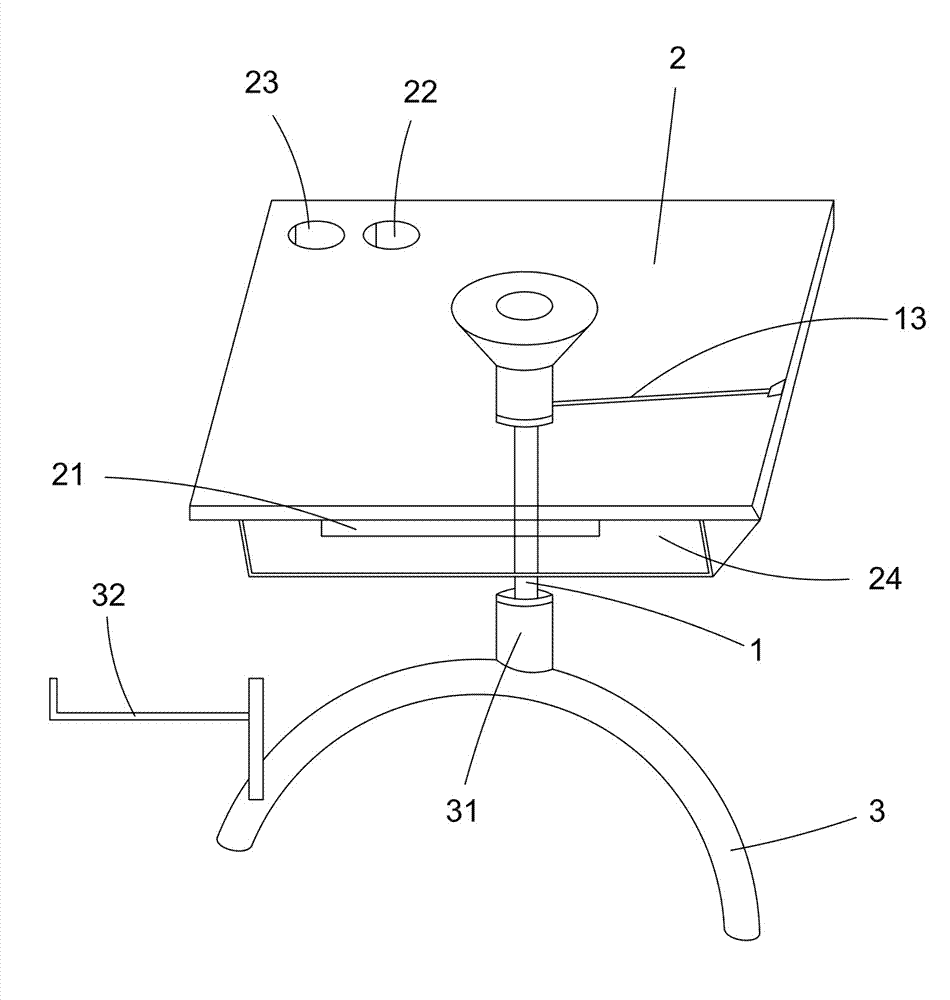
Figure 1 is a schematic diagram of the utility model.
Figure 2 shows the model without the tabletop.
Figure 3 is a sectional view of the guiding tube and gas spring.
Figure 4 is a sectional view of the table frame.
Detailed Implementation As shown in Figures 1 and 2, the utility model includes a tabletop 2 and a table frame 3. The tabletop 2 is supported by a rigid lockable gas spring 1, powered by nitrogen and using liquid oil as a locking medium. The rigid lockable gas spring 1 has a movable end 11 for the tabletop and a fixed part 12 for the frame. It is also connected to an adjustment device 13 for positioning the movable end 11. The tabletop 2 may include additional features like a sliding keyboard tray 21, pen holders 22, and cup holders 23.
Detailed connections of the rigid lockable gas spring 1 and other components are shown in Figures 2 and 3. The movable end 11 is connected to the fixed frame 14, which includes a disk-shaped bracket 144 for tabletop contact and a guiding tube 145. The guiding tube 145 is mounted on the gas spring 1, and the movable end 11 is fixed in place using a positioning block 142 and a nut 143.
As shown in Figures 1 and 4, the table frame 3 has a positioning sleeve 31 for fixing the gas spring 1, a stand 32 for a computer case, a sliding keyboard tray 21, and storage compartments 24. The adjustment device 13 can be a button or lever, placed conveniently on the table.
The model can be scaled for different users, with larger sizes for adults and smaller sizes for children. Adjusting the tabletop 2 is easy with minimal force using the adjustment device 13 for lowering, and lifting the tabletop by hand for raising. The elastic principle of the gas spring allows for smooth height adjustments, making single-person operation straightforward and eliminating the need for pins.
The movable end 11 is not limited to connecting the tabletop 2. It can also refer to other components, such as extending rods 111 fixed to the positioning sleeve 31 on the table frame 3, within the protection scope of this utility model.
Claims (9) – A Table with Adjustable Height, Easy Activation, and Rigid Locking, invented by LeiYan Gas Spring, a pioneer Chinese Gas Spring Manufacturer
- A Table with Adjustable Height, Easy Activation, and Rigid Locking, including a tabletop (2) and a table frame (3). It is characterized by: the tabletop (2) is supported on the table frame (3) by a rigid lockable gas spring (1). The rigid lockable gas spring (1) has a movable end (11) for supporting the tabletop (2) and a fixed part (12) for supporting on the table frame (3). The rigid lockable gas spring (1) is also connected to an adjustment device (13) for positioning and lifting the movable end (11) vertically.
- According to claim 1, characterized by: the tabletop (2) is provided with a fixed frame (14) connected to the movable end (11).
- According to claim 2, characterized by: the fixed frame (14) includes a bracket (144) and a guiding tube (145). The bracket (144) is disk-shaped for contacting and fixing the tabletop (2).
- According to claim 3, characterized by: the guiding tube (145) is provided with a positioning block (142) for interlocking the movable end (11).
- According to claim 4, characterized by: the movable end (11) is fixed to the positioning block (142) with a nut (143).
- According to claim 1, characterized by: the table frame (3) is provided with a positioning sleeve (31) for mounting the fixed part (12).
- According to claim 1, characterized by: the table frame (3) is provided with a computer case stand (32).
- According to claim 1, characterized by: the tabletop (2) is provided with a sliding keyboard tray (21) and storage compartments (24).
- According to claim 1, characterized by: the tabletop (2) is provided with pen holders (22) and cup holders (23).
Lockable Gas Spring with a Rigid Compression Direction
Patent No.:CN201487112U Date:2009-06-15
Google Patent: https://patents.google.com/patent/CN201487112U/en?oq=CN201487112U
China Patent: http://epub.cnipa.gov.cn/
Abstract
This utility model relates to a lockable gas spring with a rigid compression direction. It includes a cylinder, a guide sealing sleeve, a rear seal, a piston, and a piston rod. The front end of the cylinder is welded with a guide sealing sleeve, and the inner chamber connects to a piston. The end is fixed with a rear seal. The piston rod passes through the guide sealing sleeve to connect with the piston. Between the guide sealing sleeve and the piston, the piston rod is equipped with a floating piston. Nitrogen is filled between the floating piston and the guide sealing sleeve, while liquid oil is filled between the floating piston and the rear seal. By filling liquid oil between the floating piston and the rear seal, compressed liquid oil fills the bottom end of the piston during compression, achieving rigidity in the compression direction, thereby expanding the application range of the gas spring.
Description
A Lockable Gas Spring with a Rigid Compression Direction
Technical Field This utility model relates to a gas spring, specifically a lockable gas spring with a rigid compression direction.
Background Technology Lockable gas springs are widely used and their functionality is becoming increasingly diverse. Traditional gas springs exhibit a soft compression direction, limiting their application range.
Utility Model Content The technical problem this utility model aims to solve is to provide a lockable gas spring with a rigid compression direction.
To solve the above technical problems, the utility model provides the following technical solution: a lockable gas spring with a rigid compression direction, comprising a cylinder, a guide sealing sleeve, a rear seal, a piston, and a piston rod. The front end of the cylinder is welded with a guide sealing sleeve, and the inner chamber connects to a piston. The end is fixed with a rear seal. The piston rod connects to the piston. The innovation lies in: the inner chamber of the cylinder is connected with a floating piston, which divides the cylinder into front and rear chambers. The front chamber is filled with nitrogen, and the rear chamber is filled with liquid oil. The piston is located in the rear chamber filled with liquid oil.
Advantages of the Utility Model By filling liquid oil between the floating piston and the rear seal, compressed liquid oil fills the bottom end of the piston during compression, achieving rigidity in the compression direction, thereby expanding the application range of the gas spring.
Description of Drawings
The figure is a schematic diagram of the structure of the lockable gas spring with a rigid compression direction.
Detailed Implementation As shown in the figure, it includes a cylinder 1, a rear seal 2, a guide sealing sleeve 3, a floating piston 6, nitrogen 10, a piston 4, a piston rod 5, a valve needle 8, an activation rod 9, and liquid oil 7.
The front end of the cylinder 1 is welded with a guide sealing sleeve 3, and the end is fixed with a rear seal 2. The inner chamber connects with a floating piston 6, which divides the inner chamber of the cylinder 1 into front and rear chambers. The front chamber is filled with nitrogen 10, and the rear chamber is filled with liquid oil 7.
The piston 4 is connected in the rear chamber filled with liquid oil 7. The specific structure is: the top end of the piston 4 is connected to the piston rod 5, which passes through the guide sealing sleeve 3. The inner chamber connects to a valve needle 8, which is connected to the activation rod 9 that passes through the piston rod 5.
During the operation of the lockable gas spring with a rigid compression direction, under the action of external force, the piston rod 5, activation rod 9, and piston 4 move downward. The activation rod 9 opens the valve needle 8, and the liquid oil 7 at the bottom end of the piston 4 flows above the piston 4, pushing the floating piston 6 and compressing the nitrogen 10 in the front chamber of the cylinder 1. At any position, closing the valve needle 8 locks the piston rod 5 and stops its movement. Since there is a portion of liquid oil 7 in the sealed space between the piston 4 and the rear seal 2, and the liquid oil in the sealed space is rigid, it achieves rigidity in the compression direction of the lockable gas spring, expanding the application range of the gas spring.
Claims (1) – Lockable Gas Spring with a Rigid Compression Direction, invented by LeiYan Gas Spring, a pioneer Chinese Gas Spring Manufacturer
- A lockable gas spring with a rigid compression direction, comprising a cylinder, a guide sealing sleeve, a rear seal, a piston, and a piston rod. The front end of the cylinder is welded with a guide sealing sleeve, and the inner chamber connects to a piston. The end is fixed with a rear seal. The piston rod connects to the piston. It is characterized by: the inner chamber of the cylinder is connected with a floating piston, which divides the cylinder into front and rear chambers. The front chamber is filled with nitrogen, and the rear chamber is filled with liquid oil. The piston is located in the rear chamber filled with liquid oil.