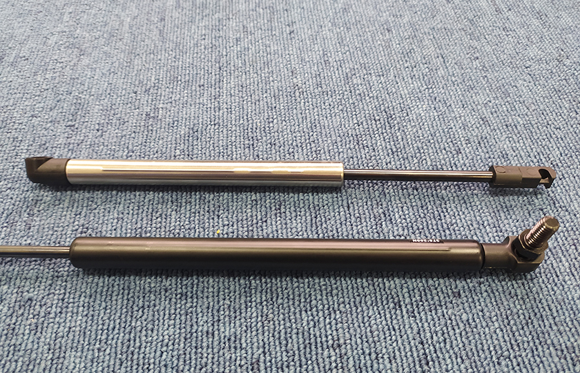
Tag: leiyan gas spring patent
A Compressible Gas Spring with an Arbitrarily Lockable Device
Patent No.:CN106090100A Date:2016-08-11
Google Patent: https://patents.google.com/patent/CN106090100A/en?oq=CN106090100A
China Patent: http://epub.cnipa.gov.cn/
A Compressible Gas Spring with an Arbitrarily Lockable Device
Abstract:
The invention relates to a compressible gas spring with an arbitrarily lockable device, which is provided with a locking device installed on the right side of the compressible gas spring. The locking device includes a fixed component that can be connected to the cylinder of the compressible gas spring and a locking component that achieves the locking of the piston rod of the compressible gas spring through the relative movement of the fixed component. The locking component is installed on the fixed component. The design of this invention is ingenious, convenient to use, sturdy, durable, and requires little external force.
Description:
A Compressible Gas Spring with an Arbitrarily Lockable Device
Technical Field: The invention relates to a compressible gas spring with an arbitrarily lockable device.
Background Technology: At present, ordinary compressible gas springs have difficulty locking in position. The compression or extension of these springs is done through an interconnected hole on the valve body piston. When a slow extension speed is required, the compression force must be increased, which becomes very heavy.
Summary of the Invention: The technical problem to be solved by this invention is to provide an arbitrarily lockable device for a compressible gas spring that is reasonably designed, compact in structure, and easy to use.
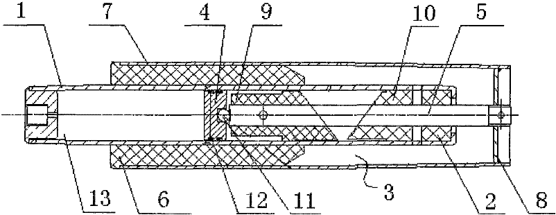
To solve the above problem, the technical solution adopted in this invention is: The basic structure of this invention includes a cylinder, a left connection piece set at the left end of the cylinder, a piston rod installed in the cylinder, a piston installed on the piston rod and located inside the cylinder, a guiding and sealing component set at the right part of the cylinder, a locking device installed on the right side of the cylinder, a right connection piece set at the right end of the piston rod, and a power source gas set inside the cylinder.
Additionally, it includes a locking device installed on the right side of the compressible gas spring. The key point is: the locking device includes a fixed component connected to the cylinder of the compressible gas spring and a locking component that achieves the locking of the piston rod of the compressible gas spring through the relative movement of the fixed component. The locking component is installed on the fixed component.
The piston rod sequentially passes through the guiding and sealing component and the locking device. The locking device includes a locking assembly sleeve on the right end of the cylinder, an end closure set at the right end of the locking assembly sleeve, a limit tube groove set between the locking assembly sleeve and the cylinder, a radial through-hole set vertically on the cylinder, a unlocking lever set vertically within the radial through-hole, a pivot point shaft set at the lower end of the outer wall of the cylinder, at least two split elastic lock blocks evenly distributed inside the cylinder, a lock block pressing sleeve set at the right side of the split elastic lock blocks, a spring set between the positioning rebate at the right end of the lock block pressing sleeve and the end closure, and an unlocking pull wire set on the outer wall of the locking assembly sleeve.
The split elastic lock blocks are configured to embrace the outer wall of the piston rod. The outer wall of the split elastic lock blocks contacts the left end rebate inner wall of the lock block pressing sleeve. An annular inner groove is set on the inner wall of the split elastic lock blocks, and a wire spring is set within the inner groove. The middle circumference of the unlocking lever surrounds the outer side of the split elastic lock blocks and is located on the left side of the lock block pressing sleeve. The upper end of the unlocking lever is connected to the pull wire head of the unlocking pull wire. The lower end of the unlocking lever passes through the radial through-hole and swings around the pivot point shaft. An oscillation gap is set between the radial through-hole and the unlocking lever along the axial direction of the locking assembly sleeve. The rightmost point of the upper end of the oscillating unlocking lever is located on the right side of the left end surface of the lock block pressing sleeve. The unlocking lever contacts the left end surface of the lock block pressing sleeve. The outer wall of the split elastic lock blocks forms an outer conical surface, and the left end rebate of the lock block pressing sleeve is equipped with an inner conical surface corresponding to the outer conical surface. The radial through-hole is a long hole set along the axial direction of the locking assembly sleeve. The length of the oscillation gap is greater than the distance between the unlocking lever and the left end surface of the lock block pressing sleeve. A sealing groove is set on the piston, and a sealing ring for sealing the piston and the inner wall of the cylinder is set within the sealing groove. The piston separates the cylinder chamber into a rod chamber and a non-rod chamber. The rod chamber is located on the right side of the non-rod chamber. A damping hole is set on the piston to communicate the sealing groove and the non-rod chamber. An air return hole is set on the piston to communicate the sealing groove and the rod chamber. A fitting gap is set between the piston and the inner wall of the cylinder. The air return hole and the damping hole respectively communicate with the bottom of the sealing groove. The guiding and sealing component includes a first sealing sleeve, a second sealing sleeve, and a third sealing sleeve sequentially set in the cylinder from left to right. Sealing rings are set between the first sealing sleeve and the second sealing sleeve, and between the second sealing sleeve and the third sealing sleeve. The first sealing sleeve, second sealing sleeve, and third sealing sleeve are respectively riveted within the right end of the cylinder chamber. A double-position sealing end plug is set at the left end of the cylinder, and the left connection piece is set at the left end of the double-position sealing end plug. The taper of the outer conical surface and the inner conical surface is either 1:5, 1:10, or 7:24.
The beneficial effects of adopting the above technical solution are as follows: The preferred design includes a return air hole and a damping hole on the piston assembly. The return air hole functions when the piston rod is compressed, while the damping hole functions when the piston rod extends. The compression force of an ordinary compressible gas spring is much greater than that of this invention. All locking components in the locking device are assembled on the locking assembly sleeve, which also serves to connect with the cylinder. The split elastic lock blocks are preferably blocks forming a complete embracing locking device with a specified internal circular diameter. The assembled embracing locking device has an outer conical surface with a specified angle. The embracing locking device is equipped with wire springs. The wire springs expand the split elastic lock blocks outward when not subjected to external force, changing the formed inner circular diameter to achieve the purpose of not embracing the piston rod. The lock block pressing sleeve and the spring are arbitrary embracing locking components. The lock block pressing sleeve acts on the split elastic lock blocks. The taper of the outer conical surface and the inner conical surface is the same. Under the action of the spring, the lock block pressing sleeve compresses the split elastic lock blocks, closing them to form an embracing locking force, locking the piston rod and stopping its extension and contraction. The unlocking of the locking device is achieved by the unlocking pull wire and unlocking lever. The unlocking lever is installed within the reserved radial through-hole of the locking assembly sleeve and is connected in a single-axis, single-end manner. It forms a mechanical lever with the pivot point shaft. The unlocking pull wire is on the other end of the unlocking lever. An external force pulls the unlocking pull wire, making the unlocking lever push the lock block pressing sleeve. The split elastic lock blocks are then expanded by the internal wire springs, opening the locking device. When the external force on the unlocking pull wire is released, the locking device locks again. The unlocking lever can also be designed as a hand-pull or handle form without using the unlocking pull wire.
This invention is ingeniously designed, easy to use, durable, and requires little external force.
Explanation of Drawings:
- Figure 1: Structural schematic diagram of the invention.
- Figure 2: Structural schematic diagram of the locking device in the invention.
- Figure 3: Structural schematic diagram of the split elastic lock block in the invention.
- Figure 4: Structural schematic diagram of the internal groove in the invention.
- Figure 5: Structural schematic diagram of the lock block pressing sleeve in the invention.
Key Components:
- Right connection piece
- Piston rod
- Locking device
- Cylinder
- Guiding and sealing component
- Piston
- Power source gas
- Double-position sealing end plug
- Left connection piece
- Damping hole
- Air return hole
- Fitting gap
- First sealing sleeve
- Second sealing sleeve
- Third sealing sleeve
- Locking assembly sleeve
- Limit tube groove
- Radial through-hole
- End closure
- Unlocking lever
- Pivot point shaft
- Split elastic lock block
- Lock block pressing sleeve
- Unlocking pull wire
- Pull wire head
- Internal groove
- Wire spring
- Outer conical surface
- Inner conical surface
- Positioning rebate
- Spring
Specific Implementation: As shown in Figures 1-5, this invention includes a cylinder (4), a left connection piece (9) set at the left end of the cylinder (4), a piston rod (2) set inside the cylinder (4), a piston (6) set on the piston rod (2) and located inside the cylinder (4), a guiding and sealing component (5) set at the right part of the cylinder (4), a locking device (3) set at the right side of the cylinder (4), a right connection piece (1) set at the right end of the piston rod (2), and a power source gas (7) set inside the cylinder (4).
The piston rod (2) sequentially passes through the guiding and sealing component (5) and the locking device (3). The locking device (3) includes a fixed component connected to the cylinder (4) of the compressible gas spring and a locking component that achieves the locking of the piston rod (2) through the relative movement of the fixed component. The locking component is installed on the fixed component.
The locking device (3) includes a locking assembly sleeve (16) on the right end of the cylinder (4), an end closure (19) set at the right end of the locking assembly sleeve (16), a limit tube groove (17) set between the locking assembly sleeve (16) and the cylinder (4), a radial through-hole (18) set vertically on the cylinder (4), a unlocking lever (20) set vertically within the radial through-hole (18), a pivot point shaft (21) set at the lower end of the outer wall of the cylinder (4), at least two split elastic lock blocks (22) evenly distributed inside the cylinder (4), a lock block pressing sleeve (23) set at the right side of the split elastic lock blocks (22), a spring (32) set between the positioning rebate (31) at the right end of the lock block pressing sleeve (23) and the end closure (19), and an unlocking pull wire (24) set on the outer wall of the locking assembly sleeve (16).
The split elastic lock blocks (22) embrace the outer wall of the piston rod (2). The outer wall of the split elastic lock blocks (22) contacts the left end rebate inner wall of the lock block pressing sleeve (23). An annular inner groove (26) is set on the inner wall of the split elastic lock blocks (22), and a wire spring (27) is set within the inner groove (26). The middle circumference of the unlocking lever (20) surrounds the outer side of the split elastic lock blocks (22) and is located on the left side of the lock block pressing sleeve (23). The upper end of the unlocking lever (20) is connected to the pull wire head (25) of the unlocking pull wire (24).
The lower end of the unlocking lever (20) passes through the radial through-hole (18) and swings around the pivot point shaft (21). An oscillation gap is set between the radial through-hole (18) and the unlocking lever (20) along the axial direction of the locking assembly sleeve (16). The rightmost point of the upper end of the oscillating unlocking lever (20) is located on the right side of the left end surface of the lock block pressing sleeve (23). The unlocking lever (20) contacts the left end surface of the lock block pressing sleeve (23). The outer wall of the split elastic lock blocks (22) forms an outer conical surface (28), and the left end rebate of the lock block pressing sleeve (23) is equipped with an inner conical surface (30) corresponding to the outer conical surface (28). The radial through-hole (18) is a long hole set along the axial direction of the locking assembly sleeve (16).
The length of the oscillation gap is greater than the distance between the unlocking lever (20) and the left end surface of the lock block pressing sleeve (23), thereby increasing the oscillation stroke to ensure complete disengagement.
A sealing groove is set on the piston (6). A sealing ring for sealing the piston (6) and the inner wall of the cylinder (4) is set within the sealing groove. The piston (6) separates the cylinder chamber into a rod chamber and a non-rod chamber. The rod chamber is located on the right side of the non-rod chamber. A damping hole (10) is set on the piston (6) to communicate the sealing groove and the non-rod chamber. An air return hole (11) is set on the piston (6) to communicate the sealing groove and the rod chamber. A fitting gap (12) is set between the piston (6) and the inner wall of the cylinder (4).
The air return hole (11) and the damping hole (10) respectively communicate with the bottom of the sealing groove.
The guiding and sealing component (5) includes a first sealing sleeve (13), a second sealing sleeve (14), and a third sealing sleeve (15) sequentially set in the cylinder (4) from left to right. Sealing rings are set between the first sealing sleeve (13) and the second sealing sleeve (14), and between the second sealing sleeve (14) and the third sealing sleeve (15). The first sealing sleeve (13), second sealing sleeve (14), and third sealing sleeve (15) are respectively riveted within the right end of the cylinder chamber.
A double-position sealing end plug (8) is set at the left end of the cylinder (4), and the left connection piece (9) is set at the left end of the double-position sealing end plug (8).
The taper of the outer conical surface (28) and the inner conical surface (30) is either 1:5, 1:10, or 7:24, achieving quick disengagement and fit.
The preferred design includes five air return holes (11) and one damping hole (10) on the piston assembly. The air return holes (11) function when the piston rod (2) is compressed, while the damping hole (10) functions when the piston rod (2) extends. The compression force of an ordinary compressible gas spring is much greater than that of this invention. All locking components in the locking device (3) are assembled on the locking assembly sleeve (16), which also serves to connect with the cylinder (4). The split elastic lock blocks (22) are preferably four blocks forming a complete embracing locking device with a specified internal circular diameter. The assembled embracing locking device has an outer conical surface (28) with a specified angle. The embracing locking device is equipped with wire springs (27). The wire springs (27) expand the split elastic lock blocks (22) outward when not subjected to external force, changing the formed inner circular diameter to achieve the purpose of not embracing the piston rod (2). The lock block pressing sleeve (23) and the spring (32) are arbitrary embracing locking components. The lock block pressing sleeve (23) acts on the split elastic lock blocks (22). The taper of the outer conical surface (28) and the inner conical surface (30) is the same. Under the action of the spring (32), the lock block pressing sleeve (23) compresses the split elastic lock blocks (22), closing them to form an embracing locking force, locking the piston rod (2) and stopping its extension and contraction. The unlocking of the locking device (3) is achieved by the unlocking pull wire (24) and unlocking lever (20). The unlocking lever (20) is installed within the reserved radial through-hole (18) of the locking assembly sleeve (16) and is connected in a single-axis, single-end manner. It forms a mechanical lever with the pivot point shaft (21). The unlocking pull wire (24) is on the other end of the unlocking lever (20). An external force pulls the unlocking pull wire (24), making the unlocking lever (20) push the lock block pressing sleeve (23). The split elastic lock blocks (22) are then expanded by the internal wire springs (27), opening the locking device. When the external force on the unlocking pull wire (24) is released, the locking device (3) locks again. The unlocking lever (20) can also be designed as a hand-pull or handle form without using the unlocking pull wire (24).
This invention is ingeniously designed, easy to use, sturdy, durable, and requires little external force.
It should be noted that the above embodiments are only used to illustrate the technical solutions of this invention and not to limit them. Although this invention has been described in detail with reference to the aforementioned embodiments, those skilled in the art should understand that they can still make modifications to the technical solutions described in the above embodiments or make equivalent replacements for some of the technical features. It is evident that those skilled in the art can combine multiple technical solutions of this invention. These modifications or replacements do not deviate from the spirit and scope of the technical solutions of the embodiments of this invention.
Claims: A Compressible Gas Spring with an Arbitrarily Lockable Device, invented by LeiYan Gas Spring, a pioneer Chinese Gas Spring Manufacture
- A compressible gas spring with an arbitrarily lockable device, characterized by the inclusion of a locking device (3) installed on the right side of the compressible gas spring. The locking device (3) includes a fixed component connected to the cylinder (4) of the compressible gas spring and a locking component that achieves the locking of the piston rod (2) of the compressible gas spring through the relative movement of the fixed component. The locking component is installed on the fixed component.
- According to claim 1, the compressible gas spring with an arbitrarily lockable device is characterized in that the locking device (3) includes a locking assembly sleeve (16) fitted on the right end of the cylinder (4), an end closure (19) set at the right end of the locking assembly sleeve (16), a limit tube groove (17) set between the locking assembly sleeve (16) and the cylinder (4), a radial through-hole (18) set vertically on the cylinder (4), a unlocking lever (20) set vertically within the radial through-hole (18), a pivot point shaft (21) set at the lower end of the outer wall of the cylinder (4), at least two split elastic lock blocks (22) evenly distributed inside the cylinder (4), a lock block pressing sleeve (23) set at the right side of the split elastic lock blocks (22), a spring (32) set between the positioning rebate (31) at the right end of the lock block pressing sleeve (23) and the end closure (19), and an unlocking pull wire (24) set on the outer wall of the locking assembly sleeve (16). The split elastic lock blocks (22) embrace the outer wall of the piston rod (2). The outer wall of the split elastic lock blocks (22) contacts the left end rebate inner wall of the lock block pressing sleeve (23). An annular inner groove (26) is set on the inner wall of the split elastic lock blocks (22), and a wire spring (27) is set within the inner groove (26). The middle circumference of the unlocking lever (20) surrounds the outer side of the split elastic lock blocks (22) and is located on the left side of the lock block pressing sleeve (23). The upper end of the unlocking lever (20) is connected to the pull wire head (25) of the unlocking pull wire (24). The lower end of the unlocking lever (20) passes through the radial through-hole (18) and swings around the pivot point shaft (21). An oscillation gap is set between the radial through-hole (18) and the unlocking lever (20) along the axial direction of the locking assembly sleeve (16). The rightmost point of the upper end of the oscillating unlocking lever (20) is located on the right side of the left end surface of the lock block pressing sleeve (23). The unlocking lever (20) contacts the left end surface of the lock block pressing sleeve (23).
- According to claim 2, the compressible gas spring with an arbitrarily lockable device is characterized in that the outer wall of the split elastic lock blocks (22) forms an outer conical surface (28), and the left end rebate of the lock block pressing sleeve (23) is equipped with an inner conical surface (30) corresponding to the outer conical surface (28).
- According to claim 3, the compressible gas spring with an arbitrarily lockable device is characterized in that the radial through-hole (18) is a long hole set along the axial direction of the locking assembly sleeve (16).
- According to claim 3, the compressible gas spring with an arbitrarily lockable device is characterized in that the length of the oscillation gap is greater than the distance between the unlocking lever (20) and the left end surface of the lock block pressing sleeve (23).
- According to claim 1, the compressible gas spring with an arbitrarily lockable device is characterized in that a left connection piece (9) is set at the left end of the cylinder (4), a guiding and sealing component (5) is set at the right part of the cylinder (4), a locking device (3) is set at the right side of the cylinder (4), a right connection piece (1) is set at the right end of the piston rod (2), and a power source gas (7) is set inside the cylinder (4). The piston rod (2) sequentially passes through the guiding and sealing component (5) and the locking device (3). A sealing groove is set on the piston (6). A sealing ring for sealing the piston (6) and the inner wall of the cylinder (4) is set within the sealing groove. The piston (6) separates the cylinder chamber into a rod chamber and a non-rod chamber. The rod chamber is located on the right side of the non-rod chamber. A damping hole (10) is set on the piston (6) to communicate the sealing groove and the non-rod chamber. An air return hole (11) is set on the piston (6) to communicate the sealing groove and the rod chamber. A fitting gap (12) is set between the piston (6) and the inner wall of the cylinder (4).
- According to claim 6, the compressible gas spring with an arbitrarily lockable device is characterized in that the air return hole (11) and the damping hole (10) respectively communicate with the bottom of the sealing groove.
- According to claim 6, the compressible gas spring with an arbitrarily lockable device is characterized in that the guiding and sealing component (5) includes a first sealing sleeve (13), a second sealing sleeve (14), and a third sealing sleeve (15) sequentially set in the cylinder (4) from left to right. Sealing rings are set between the first sealing sleeve (13) and the second sealing sleeve (14), and between the second sealing sleeve (14) and the third sealing sleeve (15). The first sealing sleeve (13), second sealing sleeve (14), and third sealing sleeve (15) are respectively riveted within the right end of the cylinder chamber.
- According to claim 6, the compressible gas spring with an arbitrarily lockable device is characterized in that a double-position sealing end plug (8) is set at the left end of the cylinder (4), and the left connection piece (9) is set at the left end of the double-position sealing end plug (8).
- According to claim 3, the compressible gas spring with an arbitrarily lockable device is characterized in that the taper of the outer conical surface (28) and the inner conical surface (30) is either 1:5, 1:10, or 7:24.
An Electrically Compressible Gas Spring
Patent No.:CN205859030U Date:2016-08-11
Google Patent: https://patents.google.com/patent/CN205859030U/en?oq=CN205859030U
China Patent: http://epub.cnipa.gov.cn/
An Electrically Compressible Gas Spring
Abstract
This utility model relates to an electrically compressible gas spring, comprising a gas spring device and a linear telescopic driving device connected to the gas spring device. The gas spring device includes a cylinder, a hollow piston rod set inside the cylinder, a piston device set on the hollow piston rod, inert gas set inside the cylinder, a guiding sealing assembly set between the right end of the cylinder and the outer side wall of the hollow piston rod, a rod chamber set on the right side of the piston device, and a non-rod chamber set on the left side of the piston device. This utility model operates smoothly and uniformly, has an optimized structure, and good manufacturability.
Description
An Electrically Compressible Gas Spring
Technical Field This utility model relates to an electrically compressible gas spring.
Background Technology Traditional gas springs use a solid round steel rod for the piston rod and a simple common rear plug, requiring a damping hole for design simplicity, which does not meet the requirements for automated and intelligent equipment.
Utility Model Content The technical problem to be solved by this utility model is to provide an electrically compressible gas spring that is reasonably designed, compact in structure, and easy to use.
To solve the above problems, the technical solution adopted by this utility model is: An electrically compressible gas spring, comprising a gas spring device and a linear telescopic driving device connected to the gas spring device.
Further, the gas spring device includes a cylinder, a hollow piston rod installed inside the cylinder, inert gas set inside the cylinder, a guiding sealing assembly set between the right end of the cylinder and the outer side wall of the hollow piston rod, a piston device set on the hollow piston rod, a rod chamber set on the right side of the piston device, and a non-rod chamber set on the left side of the piston device; the piston device is located on the left side of the guiding sealing assembly.
Further, the linear telescopic driving device includes a sealed guiding tube set inside the cylinder, a screw nut, and a guiding ring set on the left end of the screw nut’s screw; the screw nut is fixed on the sealed guiding tube, and the screw nut’s screw is set to extend and retract synchronously with the hollow piston rod; the guiding ring is set inside the sealed guiding tube, which is sealed with the inner cavity of the cylinder, the screw nut, sealed guiding tube, and cylinder’s inner hole, as well as the hollow piston rod, are coaxially set.
Further, the sealed guiding tube is sealed with the inner cavity of the cylinder through the piston device.
Further, the right end of the screw nut’s screw is connected to a reduction device, which is connected to a motor. The motor’s wiring port is connected to a power source, and the right end of the hollow piston rod is clamped onto the reduction device.
Further, the reduction device is a straight-tooth reducer, with the right end of the screw nut’s screw connected to the reduction device’s output hole through an anti-disassembly snap ring.
Further, a rear plug is sealed at the left end of the cylinder, located at the left end of the sealed guiding tube, and integrated.
Further, the piston device includes a piston set on the hollow piston rod, a hole sealing ring set between the inner side wall of the piston and the outer side wall of the sealed guiding tube, and/or a second shaft sealing ring set between the inner side wall of the piston and the outer side wall of the sealed guiding tube, a first shaft sealing ring set between the outer side wall of the piston and the inner side wall of the cylinder, an annular groove set on the outer side wall of the piston for placing the first shaft sealing ring, a vent hole set on the piston, and a fitting gap set between the outer side wall of the piston and the inner side wall of the cylinder; the rod chamber and the non-rod chamber correspond to the bottom of the annular groove through the vent hole.
Further, as shown in Figure 3, a directional guiding outer sleeve coaxially set with the hollow piston rod is clamped at the right end of the cylinder; the reduction device and the motor are slidably set inside the directional guiding outer sleeve through the screw nut.
Further, the screw nut’s screw has at least two threads, and a sealing stop ring for fixing the hole sealing ring is set at the left end of the piston.
Advantages: This utility model drives the hollow piston rod to reciprocate in the cylinder through the motor, reduction device, and screw nut, with the guiding ring providing support and guidance. The sealed guiding tube reduces the overall size, ensuring a reasonable structure and scientific design. The first shaft sealing ring, fitting gap, and vent hole enable ventilation, resulting in smooth and uniform operation, optimized structure, and good manufacturability.
Drawings:
- Figure 1: Structural schematic diagram of this utility model.
- Figure 2: Structural schematic diagram of the piston device in this utility model.
- Figure 3: Structural schematic diagram of a variation of this utility model.
Components:
- Hollow piston rod
- Cylinder
- Guiding sealing assembly
- Piston device
- Inert gas
- Rear plug
- Hole sealing ring
- Screw nut
- Guiding ring
- Reduction device
- Wiring port
- Motor
- Directional guiding outer sleeve
- Anti-disassembly snap ring
- Sealed guiding tube
- Rod chamber
- Non-rod chamber
- First shaft sealing ring
- Fitting gap
- Vent hole
- Piston
- Sealing stop ring
Specific Implementation: As shown in Figures 1-3, this utility model includes a gas spring device and a linear telescopic driving device connected to the gas spring device.
Further, the gas spring device includes a cylinder 2, a hollow piston rod 1 installed inside the cylinder 2, inert gas 5 set inside the cylinder 2, a guiding sealing assembly 3 set between the right end of the cylinder 2 and the outer side wall of the hollow piston rod 1, a piston device 4 set on the hollow piston rod 1, a rod chamber 16 set on the right side of the piston device 4, and a non-rod chamber 17 set on the left side of the piston device 4; the piston device 4 is located on the left side of the guiding sealing assembly 3.
Further, the linear telescopic driving device includes a sealed guiding tube 15 set inside the cylinder 2, a screw nut 8, and a guiding ring 9 set on the left end of the screw nut 8’s screw; the screw nut 8 is fixed on the sealed guiding tube 15, and the screw nut 8’s screw is set to extend and retract synchronously with the hollow piston rod 1; the guiding ring 9 is set inside the sealed guiding tube 15, which is sealed with the inner cavity of the cylinder 2, the screw nut 8, sealed guiding tube 15, and cylinder 2’s inner hole, as well as the hollow piston rod 1, are coaxially set.
Further, the sealed guiding tube 15 is sealed with the inner cavity of the cylinder 2 through the piston device 4.
Further, the right end of the screw nut 8’s screw is connected to a reduction device 10, which is connected to a motor 12. The motor 12’s wiring port 11 is connected to a power source, and the right end of the hollow piston rod 1 is clamped onto the reduction device 10.
Further, the reduction device 10 is a straight-tooth reducer, with the right end of the screw nut 8’s screw connected to the reduction device 10’s output hole through an anti-disassembly snap ring 14.
Further, a rear plug 6 is sealed at the left end of the cylinder 2, located at the left end of the sealed guiding tube 15, and integrated.
Further, the piston device 4 includes a piston 21 set on the hollow piston rod 1, a hole sealing ring 7 set between the inner side wall of the piston 21 and the outer side wall of the sealed guiding tube 15, and/or a second shaft sealing ring set between the inner side wall of the piston 21 and the outer side wall of the sealed guiding tube 15, a first shaft sealing ring 18 set between the outer side wall of the piston 21 and the inner side wall of the cylinder 2, an annular groove set on the outer side wall of the piston 21 for placing the first shaft sealing ring 18, a vent hole 20 set on the piston 21, and a fitting gap 19 set between the outer side wall of the piston 21 and the inner side wall of the cylinder 2; the rod chamber 16 and the non-rod chamber 17 correspond to the bottom of the annular groove through the vent hole 20.
Further, as shown in Figure 3, a directional guiding outer sleeve 13 coaxially set with the hollow piston rod 1 is clamped at the right end of the cylinder 2; the reduction device 10 and the motor 12 are slidably set inside the directional guiding outer sleeve 13 through the screw nut 8.
Further, the screw nut’s screw has at least two threads, and a sealing stop ring for fixing the hole sealing ring is set at the left end of the piston. Components:
- Hollow piston rod 1
- Cylinder 2
- Guiding sealing assembly 3
- Piston device 4
- Inert gas 5
- Rear plug 6
- Hole sealing ring 7
- Screw nut 8
- Guiding ring 9
- Reduction device 10
- Wiring port 11
- Motor 12
- Directional guiding outer sleeve 13
- Anti-disassembly snap ring 14
- Sealed guiding tube 15
- Rod chamber 16
- Non-rod chamber 17
- First shaft sealing ring 18
- Fitting gap 19
- Vent hole 20
- Piston 21
- Sealing stop ring 22
This utility model is particularly suitable for electric car tailgate rods. The hollow piston rod 1 is made of hollow precision-drawn steel pipe. The rear plug 6 and the sealed guiding tube 15 are made by welding a section of precision-drawn steel pipe on the inner end of the rear plug 6, thereby extending the life of the electric gas spring, reducing wear, and minimizing the overall size. With the effect of the second shaft sealing ring and/or the hole sealing ring 7 on the piston device 4, it isolates the mechanical assembly and movement space of the electric control gas spring. The electric gas spring performance in terms of lifespan and friction is thus improved.
The linear telescopic driving device can use existing electric push rods or other common linear reciprocating mechanisms. The screw threads of the screw nut 8 are determined according to actual needs to improve service life. The piston device 4 does not require a damping hole, and the shared vent hole 20 can be used since its bidirectional movement is driven by the electric components. The opening and closing speeds depend on the number of screw threads in the screw nut 8, and both opening and closing are at a uniform speed.
The hollow piston rod 1, rear plug 6, and sealed guiding tube 15 are the core of this utility model. The hole sealing ring 7, the second shaft sealing ring, and the guiding ring 9 are key to ensuring the performance of the electric gas spring.
This utility model drives the hollow piston rod 1 to reciprocate in the cylinder 2 through the motor 12, reduction device 10, and screw nut 8, with the guiding ring 9 providing support and guidance. The sealed guiding tube 15 reduces the overall size, ensuring a reasonable structure and scientific design. The first shaft sealing ring 18, fitting gap 19, and vent hole 20 enable ventilation, resulting in smooth and uniform operation, optimized structure, and good manufacturability.
It should be noted that the above embodiments are only for illustrating the technical solutions of this utility model, not for limiting them. Although the utility model has been described in detail with reference to the foregoing embodiments, those skilled in the art should understand that they can still modify the technical solutions described in the foregoing embodiments or make equivalent replacements for some of the technical features. These modifications or replacements do not deviate from the spirit and scope of the corresponding technical solutions of this utility model.
Claims (10) – An Electrically Compressible Gas Spring, invented by LeiYan Gas Spring, a pioneer Chinese Gas Spring Manufacturer
- An electrically compressible gas spring, characterized by: including a gas spring device and a linear telescopic driving device connected to the gas spring device.
- According to claim 1, characterized by: the gas spring device includes a cylinder (2), a hollow piston rod (1) installed inside the cylinder (2), inert gas (5) set inside the cylinder (2), a guiding sealing assembly (3) set between the right end of the cylinder (2) and the outer side wall of the hollow piston rod (1), a piston device (4) set on the hollow piston rod (1), a rod chamber (16) set on the right side of the piston device (4), and a non-rod chamber (17) set on the left side of the piston device (4); the piston device (4) is located on the left side of the guiding sealing assembly (3).
- According to claim 2, characterized by: the linear telescopic driving device includes a sealed guiding tube (15) set inside the cylinder (2), a screw nut (8), and a guiding ring (9) set on the left end of the screw nut (8)’s screw; the screw nut (8) is fixed on the sealed guiding tube (15), and the screw nut’s screw is set to extend and retract synchronously with the hollow piston rod (1); the guiding ring (9) is set inside the sealed guiding tube (15), which is sealed with the inner cavity of the cylinder (2); the screw nut (8), sealed guiding tube (15), and the cylinder (2)’s inner hole, as well as the hollow piston rod (1), are coaxially set.
- According to claim 3, characterized by: the sealed guiding tube (15) is sealed with the inner cavity of the cylinder (2) through the piston device (4).
- According to claim 4, characterized by: the right end of the screw nut’s screw is connected to a reduction device (10), which is connected to a motor (12). The motor’s wiring port (11) is connected to a power source, and the right end of the hollow piston rod (1) is clamped onto the reduction device (10).
- According to claim 5, characterized by: the reduction device (10) is a straight-tooth reducer, with the right end of the screw nut’s screw connected to the reduction device’s output hole through an anti-disassembly snap ring (14).
- According to claim 6, characterized by: a rear plug (6) is sealed at the left end of the cylinder (2), located at the left end of the sealed guiding tube (15), and integrated.
- According to claim 7, characterized by: the piston device (4) includes a piston (21) set on the hollow piston rod (1), a hole sealing ring (7) set between the inner side wall of the piston (21) and the outer side wall of the sealed guiding tube (15), and/or a second shaft sealing ring set between the inner side wall of the piston (21) and the outer side wall of the sealed guiding tube (15), a first shaft sealing ring (18) set between the outer side wall of the piston (21) and the inner side wall of the cylinder (2), an annular groove set on the outer side wall of the piston (21) for placing the first shaft sealing ring (18), a vent hole (20) set on the piston (21), and a fitting gap (19) set between the outer side wall of the piston (21) and the inner side wall of the cylinder (2); the rod chamber (16) and the non-rod chamber (17) correspond to the bottom of the annular groove through the vent hole (20).
- According to claim 8, characterized by: a directional guiding outer sleeve (13) coaxially set with the hollow piston rod (1) is clamped at the right end of the cylinder (2); the reduction device (10) and the motor (12) are slidably set inside the directional guiding outer sleeve (13) through the screw nut (8).
- According to claim 8, characterized by: the screw nut’s screw has at least two threads, and a sealing stop ring (22) for fixing the hole sealing ring (7) is set at the left end of the piston (21).
A Dual Sealing Structure Gas Spring with simultaneous Inflation and Sealing
Patent No.:CN206268354U Date:2016-08-11
Google Patent: https://patents.google.com/patent/CN206268354U/en?oq=CN206268354U
China Patent: http://epub.cnipa.gov.cn/
Abstract
This utility model relates to a gas spring with Dual Sealing Structure Gas Spring with simultaneous Inflation and Sealing. It includes a cylinder, a rear plug installed in the left end of the cylinder’s inner hole, and at least one set of sealing rings installed between the outer wall of the rear plug and the inner wall of the cylinder. The piston structure of this utility model is reasonable and operates stably, ensuring precise and consistent inflation force, improving the sealing performance and service life of the guiding sealing assembly.
Description
A Dual Sealing Structure Gas Spring with simultaneous Inflation and Sealing
Technical Field This utility model relates to A Dual Sealing Structure Gas Spring with simultaneous Inflation and Sealing.
Background Technology Currently, the gas spring described in “CN201120169308.0 – Repairable Gas Spring” cannot achieve direct empty cylinder inflation, resulting in inaccurate inflation amounts and subsequent gas or oil leakage. Existing gas springs typically use a sealing guide section with a welded rear plug after inflation, resulting in a short lifespan for the sealing rings.
Utility Model Content The technical problem this utility model aims to solve is to provide A Dual Sealing Structure Gas Spring with simultaneous Inflation and Sealing that is reasonably designed, compact in structure, and convenient to use.
To solve the above problems, the technical solution adopted in this utility model is as follows: A Dual Sealing Structure Gas Spring with simultaneous Inflation and Sealing, including a cylinder, a rear plug installed in the left end of the cylinder’s inner hole, and at least one set of sealing rings installed between the outer wall of the rear plug and the inner wall of the cylinder.
Further improvements:
- At least one annular groove for placing the sealing ring is set on the outer wall of the rear plug.
- A sealing groove is set on the rear plug, and a left sealing end is set at the left end of the cylinder, hooking into the sealing groove.
- A piston rod is installed inside the cylinder, and a guiding sealing assembly is set at the right end of the cylinder, including sequentially installed first lip seal, middle seal spacer, and second lip seal guiding sleeve from left to right within the cylinder. A buffer pressure-free sealing area is formed between the first lip seal and the middle seal spacer, and between the middle seal spacer and the second lip seal guiding sleeve.
- The right end of the cylinder is set with a right sealing end. The second sealing guiding sleeve has a right sealing annular groove, hooking into the right sealing annular groove.
- The outer side wall of the middle seal spacer is press-fitted with the inner side wall of the cylinder.
- A piston rod is installed inside the cylinder, with a piston and piston plate set on the piston rod, dividing the cylinder chamber into a rod chamber on the right and a non-rod chamber on the left. The piston and piston plate are tightly riveted on the piston rod. A fitting gap is set between the inner side wall of the cylinder and the outer side wall of the piston. A sealing groove is set between the right side of the piston and the left side of the piston plate. Damping holes and O-rings are set on the piston, and ventilation grooves are set on the piston plate.
- The ventilation grooves are centripetal grooves, dividing the piston plate into three or more odd or even blades.
- The ventilation grooves can be centripetal arcs or long curves.
- A left connecting piece is installed at the left end of the rear plug, and a right connecting piece is installed at the right end of the piston rod.
Advantages:
- The piston structure of this utility model is reasonable and operates stably.
- Ventilation grooves divide the piston plate into helical blade structures, improving rigidity and ensuring stable ventilation.
- This utility model adopts post-inflation sealing and riveting. Additional O-rings are added to the rear plug. When the rear plug and cylinder are separated, the inner cavity of the empty cylinder is high-pressure sealed and inflated, ensuring consistent inflation volume and accurate gas spring force values. Immediately after cylinder inflation, the sealing mold of the high-pressure inflation device, i.e., the left and right sealing molds, push the rear plug into the cylinder and simultaneously seal it.
- The piston plate is a new five-pointed daisy piston plate. The five points of the daisy piston improve the concentricity of the piston rod, guiding sealing assembly, cylinder, piston, and piston plate, ensuring more stable operation of the gas spring.
- The guiding sealing assembly adopts secondary pressure-free sealing. Pressure-free sealing means there is initially no pressure between the first seal and the second seal due to simultaneous inflation and sealing. The first seal blocks the pressure, and the second seal, not being pressurized, creates negligible friction on the piston rod. As the gas spring operates, the surface of the piston rod accumulates a reasonable oil film, gradually pressurizing the second seal, thus improving the sealing performance and lifespan of the guiding sealing assembly.
- This structural form can be widely applied to any type of gas spring.
Description of Drawings
- Figure 1: Schematic diagram of the gas spring structure with the rear plug to be assembled.
- Figure 2: Partial schematic diagram of the left side of the assembled gas spring.
- Figure 3: Schematic diagram of the piston plate structure.
- Figure 4: Right view schematic diagram of the piston plate structure.
- Figure 5: Schematic diagram of the gas spring assembly equipment.
- Figure 6: Schematic diagram of the inflation gas circuit.
- Figure 7: Schematic diagram of the sealing oil circuit.
- Figure 8: Schematic diagram of the clamping scheme 1 oil circuit.
- Figure 9: Schematic diagram of the clamping scheme 2 gas circuit.
Components:
1.Cylinder
2.Piston rod
3.Right connecting piece
4.Left connecting piece
5.Rear plug
6.Sealing ring
7.Piston
8.Damping hole
9.Sealing groove
10.Piston plate
11.First lip seal
12.Fitting gap
13.Ventilation groove
14.Middle seal spacer
15.Second lip seal guiding sleeve
16.Left sealing end
17.Sealing groove
101.Gas spring to be assembled
102.Base
103.Lowering cylinder or hydraulic cylinder
104.Movable lowering seat
105.Upper half-round replaceable frame
106.Lower half-round replaceable frame
107.Left push-in hydraulic cylinder
108.Replaceable left push-in inflation seat
110.Inflation channel
111.End face sealing ring
112.Left sealing mold
113.Inflation sealing face
114.Right push-in sealing hydraulic cylinder
115.Right sealing mold
116.High-pressure inflation pump
117.Two-position three-way solenoid valve
118.Electronic pressure gauge
119.Sealing oil pump
120.Sealing push-in two-position four-way solenoid valve
121.Clamping oil pump
122.Clamping three-position four-way solenoid valve
123.Balancing circuit
124.Oil replenishing check valve
Detailed Implementation As shown in Figures 1-4, this embodiment of A Dual Sealing Structure Gas Spring with simultaneous Inflation and Sealing includes a cylinder 1, a rear plug 5 installed in the left end of the cylinder 1’s inner hole, and at least one set of sealing rings 6 installed between the outer wall of the rear plug 5 and the inner wall of the cylinder 1.
At least one annular groove for placing the sealing ring 6 is set on the outer wall of the rear plug 5. A sealing groove 17 is set on the rear plug 5, with a left sealing end 16 at the left end of the cylinder 1, hooking into the sealing groove 17.
A piston rod 2 is installed inside the cylinder 1, with a guiding sealing assembly set at the right end of the cylinder 1, including sequentially installed first lip seal 11, middle seal spacer 14, and second lip seal guiding sleeve 15 from left to right within the cylinder 1. A buffer pressure-free sealing area is formed between the first lip seal 11 and the middle seal spacer 14, and between the middle seal spacer 14 and the second lip seal guiding sleeve 15.
The right end of the cylinder 1 is set with a right sealing end. The second sealing guiding sleeve 15 has a right sealing annular groove, hooking into the right sealing annular groove.
The outer side wall of the middle seal spacer 14 is press-fitted with the inner side wall of the cylinder 1.
A piston rod 2 is installed inside the cylinder 1, with a piston 7 and piston plate 10 set on the piston rod 2. The piston 7 divides the cylinder 1 chamber into a rod chamber on the right and a non-rod chamber on the left. The piston 7 and piston plate 10 are tightly riveted on the piston rod 2. A fitting gap 12 is set between the inner side wall of the cylinder 1 and the outer side wall of the piston 7. A sealing groove 9 is set between the right side of the piston 7 and the left side of the piston plate 10. Damping holes 8 and O-rings are set on the piston 7, and ventilation grooves 13 are set on the piston plate 10.
The ventilation grooves 13 are centripetal grooves, dividing the piston plate 10 into three or more odd or even blades. The ventilation grooves 13 can be centripetal arcs or long curves.
A left connecting piece 4 is installed at the left end of the rear plug 5, and a right connecting piece 3 is installed at the right end of the piston rod 2.
The preferred annular groove for placing the sealing ring 6 is two, with one sealing ring 6 installed in each groove. This structure is reasonable and provides good sealing effect.
The right sealing end hooks into the right sealing annular groove. The sealing groove 17 and left sealing end 16 hook together, making assembly convenient, free of welding deformation, precise, reasonable in structure, and long-lasting.
The guiding sealing assembly includes sequentially installed first lip seal 11, middle seal spacer 14, and second lip seal guiding sleeve 15 within the cylinder 1 from left to right, ensuring a reasonable structure and long life.
The outer side wall of the middle seal spacer 14 is press-fitted firmly with the inner side wall of the cylinder 1.
The piston structure of this utility model is reasonable and operates stably.
The ventilation grooves 13 divide the piston plate 10 into helical blade structures, improving rigidity and ensuring stable ventilation.
This utility model adopts post-inflation sealing and riveting. Additional O-rings are added to the rear plug 5. When the rear plug 5 and cylinder 1 are separated, the inner cavity of the empty cylinder 1 is high-pressure sealed and inflated, ensuring consistent inflation volume and accurate gas spring force values. Immediately after cylinder inflation, the sealing mold of the high-pressure inflation device, i.e., the left and right sealing molds 112 and 115, push the rear plug 5 into the cylinder 1 and simultaneously seal it.
The piston plate 10 is a new five-pointed daisy piston plate. The five points of the daisy piston improve the concentricity of the piston rod 2, guiding sealing assembly, cylinder 1, piston 7, and piston plate 10, ensuring more stable operation of the gas spring.
The guiding sealing assembly adopts secondary pressure-free sealing. Pressure-free sealing means there is initially no pressure between the first and second seals due to simultaneous inflation and sealing. The first seal blocks the pressure, and the second seal, not being pressurized, creates negligible friction on the piston rod. As the gas spring operates, the surface of the piston rod accumulates a reasonable oil film, gradually pressurizing the second seal, thus improving the sealing performance and lifespan of the guiding sealing assembly.
This structural form can be widely applied to any type of gas spring.
As shown in Figures 5-9, the equipment for assembling A Dual Sealing Structure Gas Spring with simultaneous Inflation and Sealing includes a base 102, a clamping device set in the middle of the base 102, and an inflation sealing device set on the left side of the base 102.
The clamping device includes a vertical lowering cylinder or hydraulic cylinder 103 installed above the middle of the base 102, a movable lowering seat 104 installed at the lower end of the lowering cylinder or hydraulic cylinder 103, an upper half-round replaceable frame 105 set at the lower end of the movable lowering seat 104, and a lower half-round replaceable frame 106 installed on the base 102.
The lower half-round replaceable frame 106 and upper half-round replaceable frame 105 clamp the horizontally set gas spring 101 to be assembled.
The inflation sealing device includes a left push-in hydraulic cylinder 107 installed at the left end of the base 102, a replaceable left push-in inflation seat 108 installed on the piston rod of the left push-in hydraulic cylinder 107, an inflation channel 110 set on the replaceable left push-in inflation seat 108, an inflation sealing face 113 set at the right end of the replaceable left push-in inflation seat 108, an end face sealing ring 111 set between the inner side of the inflation sealing face 113 and the left end face of the left sealing mold 112, a left sealing mold 112 set inside the inflation sealing face 113, and an inflation through hole 110 set inside the replaceable left push-in inflation seat 108.
The inflation through hole 110 is located at the left end of the left sealing mold 112.
The replaceable left push-in inflation seat 108 has a positioning face for placing the rear plug 5. During inflation, the inflation channel 110, left sealing mold 112, central hole of the left sealing mold 112, and the left non-rod chamber of the cylinder 1 are connected for inflation.
The rear plug 5 of the gas spring 101 to be assembled is placed inside the inflation channel 110. The assembly stroke of the rear plug 5 is less than the distance between the inner side face of the step hole and the mold sealing ring.
The rear plug 5, cylinder 1, left sealing mold 112, lower half-round replaceable frame 106, and upper half-round replaceable frame 105 are coaxially set.
The equipment also includes a right push-in sealing device set on the right side of the base 102.
The right push-in sealing device includes a right push-in sealing hydraulic cylinder 114 and a guiding seat set at the left end of the piston rod of the right push-in sealing hydraulic cylinder 114.
A right sealing mold 115 is set inside the left end of the guiding seat, corresponding to the right sealing end of the cylinder 1. The cylinder body and piston rod of the right push-in sealing hydraulic cylinder 114 have through holes for the piston rod 2 of the gas spring 101 to pass through.
The right sealing mold 115 has a through hole for the piston rod 2. A step hole is set on the left side of the right sealing mold 115, with the connection root for the right sealing end of the cylinder 1 set between the inner side wall of the step hole and the inner side face of the step hole. The connection root is set as an inner chamfer or inner round corner.
Equipment for a Gas Spring with Dual Sealing Structure
The upper half-round replaceable frames 105 are arranged in two groups and set at the left and right ends of the movable lowering seat 104, while the lower half-round replaceable frames 106 are arranged in two groups and correspond to the structure of the upper half-round replaceable frames 105.
As shown in Figures 6-9, the equipment also includes a control system. The control system comprises clamping oil or gas circuits, right push-in sealing oil circuits, left push-in sealing oil circuits, and inflation gas circuits.
As shown in Figures 8 and 9, respectively representing oil and gas control, the clamping oil or gas circuit includes a clamping pump 121 connected to the oil tank or atmosphere, a lowering cylinder or hydraulic cylinder 103, and a clamping three-position four-way solenoid valve 122.
The outlet of the clamping pump 121 connects to an inlet of the clamping three-position four-way solenoid valve 122, while another inlet connects to the oil tank or atmosphere. The outlet of the clamping three-position four-way solenoid valve 122 connects to the rodless chamber of the lowering cylinder or hydraulic cylinder 103, and another outlet connects to the rod chamber.
As shown in Figure 7, the left push-in sealing oil circuit includes a left push-in hydraulic cylinder 107, a sealing oil pump 119 connected to the oil tank, and a sealing push-in two-position four-way solenoid valve 120. The sealing oil pump 119 connects to an inlet of the sealing push-in two-position four-way solenoid valve 120, while another inlet connects to the oil tank. Another outlet of the sealing push-in two-position four-way solenoid valve 120 connects to the right rod chamber of the left push-in hydraulic cylinder 107. The right push-in sealing oil circuit has the same structure as the left push-in sealing oil circuit.
As shown in Figure 6, the inflation gas circuit includes a high-pressure inflation pump 116, a two-position three-way solenoid valve 117, an inflation channel 110, the non-rod chamber of the gas spring 101 to be assembled, and an electronic pressure gauge 118. The high-pressure inflation pump 116, the two-position three-way solenoid valve 117, the inflation channel 110, and the non-rod chamber of the gas spring 101 to be assembled are sequentially connected. The electronic pressure gauge 118 is set on the inflation channel 110.
The control system also includes time relays or logic controllers to control the respective coil power-on and power-off times and sequences of the clamping three-position four-way solenoid valve 122, the sealing push-in two-position four-way solenoid valve 120, and the two-position three-way solenoid valve 117.
A balancing circuit 123 is set between the clamping three-position four-way solenoid valve 122 and the rod chamber of the lowering cylinder or hydraulic cylinder 103, or a two-way hydraulic lock is set between the clamping three-position four-way solenoid valve 122 and the lowering cylinder or hydraulic cylinder 103. An oil replenishing circuit is set between the oil tank and the rodless chamber of the lowering cylinder or hydraulic cylinder 103, including a compensating check valve 124 between the oil tank and the rodless chamber.
The middle position function of the clamping three-position four-way solenoid valve 122 is M type.
The upper half-round replaceable frames 105 are arranged in two groups and set at the left and right ends of the movable lowering seat 104, while the lower half-round replaceable frames 106 are arranged in two groups and correspond to the structure of the upper half-round replaceable frames 105.
The clamping device can use a three-jaw or four-jaw chuck for clamping, which can be manually, mechanically, or pneumatically driven. The preferred structure is shown in Figure 5.
The lower half-round replaceable frame 106 and the upper half-round replaceable frame 105 have a reasonable clamping structure, are durable, accurate in positioning, efficient in operation, firmly clamped, and highly expandable.
The inflation sealing device can use hot or cold riveting, with cold riveting preferred.
According to different customer requirements for sealing size and shape, the connection root is set as an inner chamfer or inner round corner. The assembly stroke of the rear plug 5 is less than the distance between the inner side face of the step hole and the mold sealing ring, ensuring continuity and rationality of the assembly work.
Coaxial setting improves assembly accuracy.
To improve assembly efficiency and optimize processes, a right push-in sealing device is added.
The through holes can expand the versatility and expandability of this equipment.
To improve the degree of automation, electric, hydraulic, or pneumatic control can also be used.
The electronic pressure gauge 118 realizes pressure monitoring, ensuring the stability and monitorability of equipment pressure.
Common balancing circuits 123 or two-way hydraulic locks ensure the stability of the lowering cylinder or hydraulic cylinder 103. The oil replenishing circuit ensures quick oil replenishment during rapid lowering.
The middle position function is M type, enabling unloading work and improving pressure holding effects.
The upper half-round replaceable frames 105 and the lower half-round replaceable frames 106 are arranged in two groups and set at the left and right ends of the movable lowering seat 104, improving coaxiality and craftsmanship.
When using this equipment to assemble the above products, the rear plug 5 is placed in the inflation channel 110, and the left sealing mold 112 and right sealing mold 115 are respectively placed in the inflation sealing face 113 and the guiding seat. The end face sealing ring 111 improves sealing. This utility model can achieve interchangeable connections through various methods, such as threaded connections, plug connections, tapered fits, or snap ring assemblies.
By setting the on-off times and sequences of each valve group through intermediate relays, time controllers, or PCL logic controllers, the gas spring 101 to be assembled is placed on the lower half-round replaceable frame 106. The clamping pump 121 is started, and the clamping three-position four-way solenoid valve 122 is powered on. The lowering cylinder or hydraulic cylinder 103 drives the upper half-round replaceable frame 105 downward through the movable lowering seat 104, clamping the gas spring 101 to be assembled.
After clamping, at the designated time A, the clamping three-position four-way solenoid valve 122 is de-energized to hold pressure, and the compensating check valve 124 quickly replenishes oil. The sealing push-in two-position four-way solenoid valve 120 is powered on for the first time, starting the sealing oil pump 119 of the left push-in hydraulic cylinder 107. The left push-in hydraulic cylinder 107 drives the replaceable left push-in inflation seat 108 to move right, and the cylinder 1 enters the step hole of the left sealing mold 112, achieving axial sealing through the sealing ring.
At the designated time B, the sealing push-in two-position four-way solenoid valve 120 is de-energized, stopping the movement, and the two-position three-way solenoid valve 117 and the high-pressure inflation pump 116 are powered on. The high-pressure inflation pump 116 enters the non-rod chamber of the cylinder 1 through the two-position three-way solenoid valve 117 and the inflation channel 110, achieving precise inflation.
When the inflation reaches the designated time C, the two-position three-way solenoid valve 117 and the high-pressure inflation pump 116 are de-energized. The sealing push-in two-position four-way solenoid valve 120 of the left push-in hydraulic cylinder 107 is powered on for the second time, starting the sealing oil pump 119 of the left push-in hydraulic cylinder 107. The left push-in hydraulic cylinder 107 continues to drive the rear plug 5 to move right and push it into the left end of the cylinder 1. Then, the replaceable left push-in inflation seat 108 continues to move right, and simultaneously the right push-in sealing hydraulic cylinder 114 pushes left. Under the action of the left push-in hydraulic cylinder 107 and the right push-in sealing hydraulic cylinder 114, the left sealing mold 112 and the right sealing mold 115 seal the cylinder 1.
At the designated time D, the two-position three-way solenoid valve 117 switches, the inflation channel 110 vents, the sealing push-in two-position four-way solenoid valve 120 switches, releasing the cylinder 1. The clamping three-position four-way solenoid valve 122 switches, allowing the cylinder 1 to be removed. Simultaneously, the left sealing mold 112 and right sealing mold 115 are fitted on the cylinder 1 sealing end, achieving simultaneous removal.
This utility model has an advanced structure, high automation, high work efficiency, durability, convenience in use, good assembly product quality, low cost, and reasonable craftsmanship.
Claims (10) – A Dual Sealing Structure Gas Spring with simultaneous Inflation and Sealing, invented by LeiYan Gas Spring, a pioneer Chinese Gas Spring Manufacturer
- A Dual Sealing Structure Gas Spring with simultaneous Inflation and Sealing, characterized by: including a cylinder (1), a rear plug (5) installed in the left end inner hole of the cylinder (1), and at least one set of sealing rings (6) installed between the outer wall of the rear plug (5) and the inner wall of the cylinder (1).
- According to claim 1, characterized by: at least one annular groove for placing the sealing ring (6) is set on the outer wall of the rear plug (5).
- According to claim 1, characterized by: a sealing groove (17) is set on the rear plug (5), and a left sealing end (16) is set at the left end of the cylinder (1), hooking into the sealing groove (17).
- According to claim 1, characterized by: a piston rod (2) is installed inside the cylinder (1), with a guiding sealing assembly set at the right end of the cylinder (1), including sequentially installed first lip seal (11), middle seal spacer (14), and second lip seal guiding sleeve (15) from left to right within the cylinder (1). A buffer pressure-free sealing area is formed between the first lip seal (11) and the middle seal spacer (14), and between the middle seal spacer (14) and the second lip seal guiding sleeve (15).
- According to claim 4, characterized by: the right end of the cylinder (1) is set with a right sealing end. The second sealing guiding sleeve (15) has a right sealing annular groove, hooking into the right sealing annular groove.
- According to claim 4, characterized by: the outer side wall of the middle seal spacer (14) is press-fitted with the inner side wall of the cylinder (1).
- According to claim 1, characterized by: a piston rod (2) is installed inside the cylinder (1), with a piston (7) and piston plate (10) set on the piston rod (2). The piston (7) divides the cylinder (1) chamber into a rod chamber on the right and a non-rod chamber on the left. The piston (7) and piston plate (10) are tightly riveted on the piston rod (2). A fitting gap (12) is set between the inner side wall of the cylinder (1) and the outer side wall of the piston (7). A sealing groove (9) is set between the right side of the piston (7) and the left side of the piston plate (10). Damping holes (8) and O-rings are set on the piston (7), and ventilation grooves (13) are set on the piston plate (10).
- According to claim 7, characterized by: the ventilation grooves (13) are centripetal grooves, dividing the piston plate (10) into three or more odd or even blades.
- According to claim 8, characterized by: the ventilation grooves (13) are centripetal arcs or long curves.
- According to claim 9, characterized by: a left connecting piece (4) is installed at the left end of the rear plug (5), and a right connecting piece (3) is installed at the right end of the piston rod (2).
A Pneumatic Seat Angle Reset Device
Patent No.:CN201468593U Date:2009-06-15
Google Patent: https://patents.google.com/patent/CN201468593U/en?oq=CN201468593U
China Patent: http://epub.cnipa.gov.cn/
A Pneumatic Seat Angle Reset Device
Abstract
This utility model relates to a reset device, particularly a pneumatic seat angle reset device. The technical problem to be solved is to provide a pneumatic seat angle reset device with low operating noise and flexible resetting. It includes a movable cylinder, a rear plug, a reset sleeve assembly, a piston rod, and an outer sleeve. The movable cylinder is fitted with an outer sleeve, with one end welded to the rear plug. The inner chamber contains a reset sleeve assembly, which connects to the outer sleeve’s end through a piston rod. The movable cylinder contains a thrust piston connected to one end of the reset sleeve assembly. The space between the thrust piston and the rear plug is filled with gas. This design ensures silent resetting, flexible rotation, and extended service life due to the O-ring on the thrust piston ensuring gas sealing performance.
Description
A Pneumatic Seat Angle Reset Device
Technical Field This utility model relates to a reset device, specifically a pneumatic seat angle reset device.
Background Technology Traditional seat reset devices use mechanical springs and end face bearings to reset seats. These devices are prone to making noise, lack flexibility, and are difficult to assemble.
Utility Model Content The technical problem to be solved is to provide a pneumatic seat angle reset device with low operating noise and flexible resetting.
To solve the above technical problems, the utility model provides a pneumatic seat angle reset device, which includes a movable cylinder, a rear plug, a reset sleeve assembly, a piston rod, and an outer sleeve. The movable cylinder is fitted with an outer sleeve, with one end welded to the rear plug. The inner chamber contains a reset sleeve assembly, which connects to the outer sleeve’s end through a piston rod. The innovation lies in the movable cylinder containing a thrust piston connected to one end of the reset sleeve assembly, with gas filling the space between the thrust piston and the rear plug as the reset power.
Further, balls are installed between the thrust piston and the reset sleeve assembly.
Further, the gas can be nitrogen or argon.
Further, the thrust piston is connected with an O-ring.
Advantages of the Utility Model The use of gas and balls ensures silent and flexible resetting, with the combination of the thrust piston and the O-ring ensuring the sealing performance of the nitrogen gas and extending the service life.
Description of Drawings
The figure is a schematic diagram of the pneumatic seat angle reset device.
Detailed Implementation As shown in the figure, it includes an outer sleeve 7, a guide sleeve 6, a bottom pad 8, a movable cylinder 1, a rear plug 2, a reset sleeve assembly 3, a piston rod 5, a thrust piston 4, balls 11, and an O-ring 12.
The front end of the outer sleeve 7 is fixedly connected to the guide sleeve 6, and the end is welded to the bottom pad 8. The outer sleeve 7 is also connected to the movable cylinder 1, which slides up and down guided by the guide sleeve 6.
The top end of the movable cylinder 1 is connected to the rear plug 2. The inner chamber contains a reset sleeve assembly 3 for resetting the seat angle. The reset sleeve assembly 3 consists of a conical movable reset sleeve 9 and a fixed reset sleeve 10, which are similar in structure. The fixed reset sleeve 10 is fixed at the end of the movable cylinder 1, and one end of the movable reset sleeve 9 is connected to the piston rod 5. The piston rod 5 passes through the fixed reset sleeve 10 and connects to the bottom pad 8 of the outer sleeve 7. The piston rod 5 and the fixed reset sleeve 10 have a sliding fit.
To ensure silent resetting, a thrust piston 4 is connected inside the movable cylinder 1, with gas 13 filling the space between the thrust piston 4 and the rear plug 2 as the reset power. During use, the movable cylinder 1 and the fixed reset sleeve 10 move downward under external force, separating the conical surfaces of the movable reset sleeve 9 and the fixed reset sleeve 10. Simultaneously, the thrust piston 4 compresses the gas 13 in the sealed movable cylinder 1. When the external force is removed, the compressed gas 13 is released, pushing the movable cylinder 1 upward. The conical surfaces of the movable reset sleeve 9 and the fixed reset sleeve 10 slide relative to each other until they overlap, completing the seat’s rotational reset silently. The gas 13 can be nitrogen, argon, or other inert gases.
To ensure more flexible and silent resetting, balls 11 are connected between the thrust piston 4 and the movable reset sleeve 9, concentrating the thrust point and minimizing resistance during rotation. Additionally, an O-ring 12 is connected between the outer circumference of the thrust piston 4 and the movable cylinder 1, enhancing the sealing performance of the movable cylinder 1 and extending the service life of the pneumatic seat angle reset device.
Claims (4) – A Pneumatic Seat Angle Reset Device, invented by LeiYan Gas Spring, a pioneer Chinese Gas Spring Manufacturer
According to claim 1, characterized by: the thrust piston is connected with an O-ring.
A pneumatic seat angle reset device, including a movable cylinder, a rear plug, a reset sleeve assembly, a piston rod, and an outer sleeve. The movable cylinder is fitted with an outer sleeve, with one end welded to the rear plug. The inner chamber contains a reset sleeve assembly, which connects to the outer sleeve’s end through a piston rod. It is characterized by: the movable cylinder contains a thrust piston connected to one end of the reset sleeve assembly, with gas filling the space between the thrust piston and the rear plug.
According to claim 1, characterized by: balls are installed between the thrust piston and the reset sleeve assembly.
According to claim 1, characterized by: the gas can be nitrogen or argon.
Lockable Gas Spring with a Rigid Compression Direction
Patent No.:CN201487112U Date:2009-06-15
Google Patent: https://patents.google.com/patent/CN201487112U/en?oq=CN201487112U
China Patent: http://epub.cnipa.gov.cn/
Abstract
This utility model relates to a lockable gas spring with a rigid compression direction. It includes a cylinder, a guide sealing sleeve, a rear seal, a piston, and a piston rod. The front end of the cylinder is welded with a guide sealing sleeve, and the inner chamber connects to a piston. The end is fixed with a rear seal. The piston rod passes through the guide sealing sleeve to connect with the piston. Between the guide sealing sleeve and the piston, the piston rod is equipped with a floating piston. Nitrogen is filled between the floating piston and the guide sealing sleeve, while liquid oil is filled between the floating piston and the rear seal. By filling liquid oil between the floating piston and the rear seal, compressed liquid oil fills the bottom end of the piston during compression, achieving rigidity in the compression direction, thereby expanding the application range of the gas spring.
Description
A Lockable Gas Spring with a Rigid Compression Direction
Technical Field This utility model relates to a gas spring, specifically a lockable gas spring with a rigid compression direction.
Background Technology Lockable gas springs are widely used and their functionality is becoming increasingly diverse. Traditional gas springs exhibit a soft compression direction, limiting their application range.
Utility Model Content The technical problem this utility model aims to solve is to provide a lockable gas spring with a rigid compression direction.
To solve the above technical problems, the utility model provides the following technical solution: a lockable gas spring with a rigid compression direction, comprising a cylinder, a guide sealing sleeve, a rear seal, a piston, and a piston rod. The front end of the cylinder is welded with a guide sealing sleeve, and the inner chamber connects to a piston. The end is fixed with a rear seal. The piston rod connects to the piston. The innovation lies in: the inner chamber of the cylinder is connected with a floating piston, which divides the cylinder into front and rear chambers. The front chamber is filled with nitrogen, and the rear chamber is filled with liquid oil. The piston is located in the rear chamber filled with liquid oil.
Advantages of the Utility Model By filling liquid oil between the floating piston and the rear seal, compressed liquid oil fills the bottom end of the piston during compression, achieving rigidity in the compression direction, thereby expanding the application range of the gas spring.
Description of Drawings
The figure is a schematic diagram of the structure of the lockable gas spring with a rigid compression direction.
Detailed Implementation As shown in the figure, it includes a cylinder 1, a rear seal 2, a guide sealing sleeve 3, a floating piston 6, nitrogen 10, a piston 4, a piston rod 5, a valve needle 8, an activation rod 9, and liquid oil 7.
The front end of the cylinder 1 is welded with a guide sealing sleeve 3, and the end is fixed with a rear seal 2. The inner chamber connects with a floating piston 6, which divides the inner chamber of the cylinder 1 into front and rear chambers. The front chamber is filled with nitrogen 10, and the rear chamber is filled with liquid oil 7.
The piston 4 is connected in the rear chamber filled with liquid oil 7. The specific structure is: the top end of the piston 4 is connected to the piston rod 5, which passes through the guide sealing sleeve 3. The inner chamber connects to a valve needle 8, which is connected to the activation rod 9 that passes through the piston rod 5.
During the operation of the lockable gas spring with a rigid compression direction, under the action of external force, the piston rod 5, activation rod 9, and piston 4 move downward. The activation rod 9 opens the valve needle 8, and the liquid oil 7 at the bottom end of the piston 4 flows above the piston 4, pushing the floating piston 6 and compressing the nitrogen 10 in the front chamber of the cylinder 1. At any position, closing the valve needle 8 locks the piston rod 5 and stops its movement. Since there is a portion of liquid oil 7 in the sealed space between the piston 4 and the rear seal 2, and the liquid oil in the sealed space is rigid, it achieves rigidity in the compression direction of the lockable gas spring, expanding the application range of the gas spring.
Claims (1) – Lockable Gas Spring with a Rigid Compression Direction, invented by LeiYan Gas Spring, a pioneer Chinese Gas Spring Manufacturer
- A lockable gas spring with a rigid compression direction, comprising a cylinder, a guide sealing sleeve, a rear seal, a piston, and a piston rod. The front end of the cylinder is welded with a guide sealing sleeve, and the inner chamber connects to a piston. The end is fixed with a rear seal. The piston rod connects to the piston. It is characterized by: the inner chamber of the cylinder is connected with a floating piston, which divides the cylinder into front and rear chambers. The front chamber is filled with nitrogen, and the rear chamber is filled with liquid oil. The piston is located in the rear chamber filled with liquid oil.