Tag: leiyan gas spring patent
Rotating and Height-Adjustable Auto-Reset Seat Lifter gas spring
Patent No.:CN101564245 Date:2009-06-15
Google Patent: https://patents.google.com/patent/CN101564245A/en?oq=CN101564245
China Patent: http://epub.cnipa.gov.cn/
A Rotating and Height-Adjustable Auto-Reset Seat Lifter gas spring
Abstract
This invention relates to a seat lifter gas spring that can achieve automatic resetting in both height adjustment and rotation. It includes an outer tube, an inner tube, a guide sealing sleeve, a valve body, and a piston. The front end of the outer tube is connected to a guide sealing sleeve, and the end is fixed with a valve body. The inner chamber connects with the inner tube, which contains a piston. The top of the piston is connected to a rotating reset block, and another identical rotating reset block is fixed at the top of the inner tube. The circumferential surface of the piston has an annular groove, which houses an O-ring. The center of the bottom line has a return air hole connecting the front and rear chambers of the piston. By setting angled cylindrical positioning blocks on the inner tube and piston, the lifter achieves rotational reset. The O-ring on the piston allows the return air hole to enable height reset, resulting in a simple structure, low manufacturing cost, strong versatility, and easy promotion.
Description
A Rotating and Height-Adjustable Auto-Reset Seat Lifter gas spring
Technical Field This invention relates to a lifter, specifically a rotating and height-adjustable auto-reset seat lifter.
Background Technology Gas springs have been widely used in medical equipment, automobiles, furniture, textile equipment, and processing industries. However, traditional gas spring seat lifters cannot achieve resetting for height adjustment or rotation, limiting their range of use.
Summary of the Invention The technical problem this invention aims to solve is to provide a seat lifter that can achieve automatic resetting for both height adjustment and rotation.
To solve the above technical problems, the invention’s technical solution is: a rotating and height-adjustable auto-reset seat lifter, comprising an outer tube, an inner tube, a guide sealing sleeve, a valve body, and a piston. The front end of the outer tube is connected to a guide sealing sleeve, and the end is fixed with a valve body. The inner chamber connects with the inner tube, which contains a piston. The top of the piston is connected to a rotating reset block, and another identical rotating reset block is fixed at the top of the inner tube. The circumferential surface of the piston has an annular groove, which houses an O-ring. The center of the bottom line has a return air hole connecting the front and rear chambers of the piston.
Further, the rotating reset block is a cylindrical block with a sloped end face, with an angle of 40-50°.
Further, the width of the annular groove is twice the diameter of the O-ring.
Advantages of the Invention By setting angled cylindrical positioning blocks on the inner tube and piston, the lifter achieves rotational reset. The O-ring on the piston allows the return air hole to enable height reset, resulting in a simple structure, low manufacturing cost, strong versatility, and easy promotion.
Description of Drawings
Figure 1 is a schematic diagram of the structure of the auto-reset seat lifter.
Figure 2 is a partial schematic diagram of the auto-reset seat lifter.
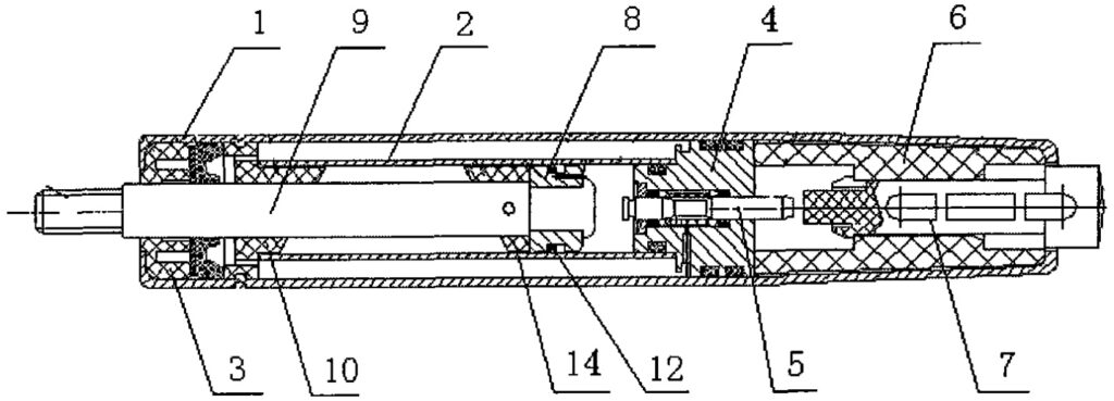
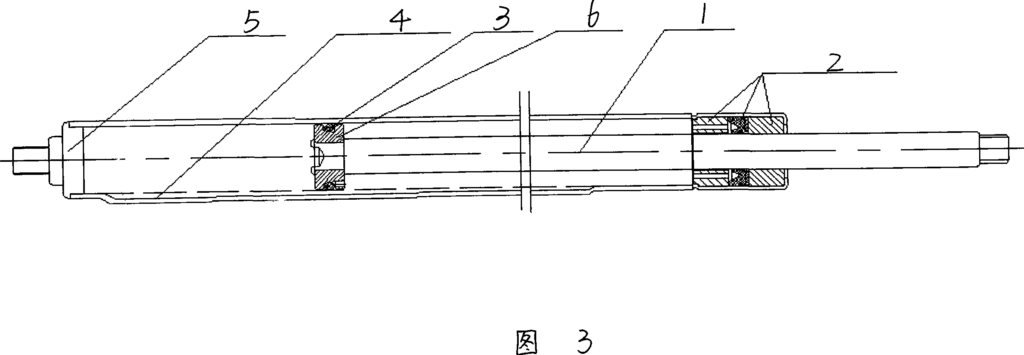
Detailed Implementation As shown in Figures 1 and 2, it includes an outer tube 1, an inner tube 2, a guide sealing sleeve 3, a valve body 4, a valve needle 5, a valve seat 6, an activation rod 7, a piston 8, a piston rod 9, a rotating reset block 10, another rotating reset block 14, an annular groove 11, and an O-ring 12.
The front end of the outer tube 1 is connected to a guide sealing sleeve 3, and the end is fixed with a valve body 4. The valve body 4 inner chamber connects with a valve needle 5, with the bottom end fixed to the valve seat 6. The valve seat 6 contains an activation rod 7, which connects with the valve needle 5 inside the valve body 4. The inner chamber of the outer tube 1 connects with an inner tube 2, which contains a piston 8. The piston 8 connects with a piston rod 9 that passes through the guide sealing sleeve 3.
To achieve horizontal rotational reset of the lifter, the top ends of the piston 8 and the inner tube 2 are connected to identical cylindrical rotating reset blocks 10 and 14 with sloped end faces. The angles of these sloped end faces are 40-50°. As shown in Figure 2, the specific working principle is: when the seat lifter activates the valve needle 5 for automatic reset, the piston 8 and its top rotating reset block 10 move upward under internal pressure. The sharp point A of the rotating reset block 10 cannot stop relative to the sharp point B of the rotating reset block 14 until point A, B’ of block 10 aligns with point A’, B of block 14, completing the rotational reset of the seat lifter.
To achieve vertical height reset of the piston rod 9, the circumferential surface of the piston 8 has an annular groove 11 with an O-ring 12. The center of the groove bottom has a return air hole 13 connecting the front and rear chambers of the piston 8. The width of the annular groove 11 is twice the diameter of the O-ring 12, and its depth is slightly less than the diameter of the O-ring 12. The working principle is: when the valve needle 5 is closed and the external force on the seat lifter is greater than or equal to the support force generated by the internal pressure of the piston 8, the O-ring 12, due to friction, rests at the C end of the annular groove 11. When the seat lifter activates the valve needle 5 for automatic reset, the O-ring 12 is forced to rest at the D end of the annular groove 11. At this time, the gas at the front end of the piston 8 enters the rear end of the piston 8 through the return air hole 13, generating an upward thrust on the piston rod 9 and piston 8, achieving the height reset of the seat.
Claims (3) Rotating and Height-Adjustable Auto-Reset Seat Lifter gas spring, invented by LeiYan Gas Spring, a pioneer Chinese Gas Spring Manufacturer
- A rotating and height-adjustable auto-reset seat lifter, comprising an outer tube, an inner tube, a guide sealing sleeve, a valve body, and a piston. The front end of the outer tube is connected to a guide sealing sleeve, and the end is fixed with a valve body. The inner chamber connects with the inner tube, which contains a piston. It is characterized by: the top of the piston is connected to a rotating reset block, and another identical rotating reset block is fixed at the top of the inner tube. The circumferential surface of the piston has an annular groove, which houses an O-ring. The center of the bottom line has a return air hole connecting the front and rear chambers of the piston.
- According to claim 1, the rotating reset block is a cylindrical block with a sloped end face, with an angle of 40-50°.
- According to claim 1, the width of the annular groove is twice the diameter of the O-ring.
A Lockable Tension Gas Spring
Patent No.:CN201487116U Date:2009-06-15
Google Patent: https://patents.google.com/patent/CN201487116U/en?oq=CN201487116U
China Patent: http://epub.cnipa.gov.cn/
Abstract
The utility model provides a lockable tension gas spring with controllable rebound after stretching. It includes a cylinder, a guide sealing sleeve, a rear plug, and a piston rod. The front end of the cylinder is fixed with a guide sealing sleeve, and the rear end is fixed with a rear plug. A fixed spacer is installed inside the cylinder. Pistons and valve body pistons are respectively arranged on the front and rear sides of the fixed spacer, and the pistons and valve body pistons are connected by a piston rod. The advantage of this structure is that a fixed spacer is added inside the cylinder, with nitrogen and liquid oil filled in the front and rear chambers, respectively. After stretching, the liquid oil enters between the valve body piston and the rear plug. Since the liquid oil is incompressible, it achieves the effect of controlling the rebound of the piston rod after the external force is removed, thus realizing the locking of the tension gas spring.
Description
A Lockable Tension Gas Spring
Technical Field The utility model relates to a gas spring, specifically a lockable tension gas spring.
Background Technology Gas springs are widely used in medical equipment, automobiles, furniture, textile equipment, and processing industries. However, there are few types of tension gas springs. Once the external force on the tension gas spring is removed, the gas spring resets, making it impossible to lock it, which limits its range of use.
Utility Model Content The technical problem this utility model aims to solve is to provide a lockable tension gas spring with controllable rebound after stretching.
To solve the above technical problems, the utility model provides a technical solution: a lockable tension gas spring, including a cylinder, a guide sealing sleeve, a rear plug, and a piston rod. The front end of the cylinder is fixed with a guide sealing sleeve, and the rear end is fixed with a rear plug. The innovation is that a fixed spacer is installed inside the cylinder, with pistons and valve body pistons respectively arranged on the front and rear sides of the fixed spacer, and the pistons and valve body pistons are connected by a piston rod.
Further, the front chamber of the fixed spacer is filled with nitrogen, and the rear chamber is filled with liquid oil.
Further, an activation rod is installed inside the piston rod, and the activation rod is fixedly connected to the valve needle of the valve body piston.
Further, a return spring is connected between the piston rod and the activation rod.
The advantages of the utility model are that a fixed spacer is added inside the cylinder, with nitrogen and liquid oil filled in the front and rear chambers, respectively. After stretching, the liquid oil enters between the valve body piston and the rear plug. Since the liquid oil is incompressible, it achieves the effect of controlling the rebound of the piston rod after the external force is removed, thus realizing the locking of the tension gas spring.
Description of Drawings
The figure is a schematic diagram of the structure of the lockable tension gas spring of the utility model.
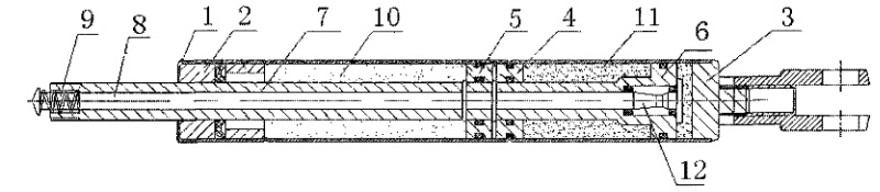
Detailed Implementation As shown in the figure, it includes a cylinder 1, guide sealing sleeve 2, rear plug 3, fixed spacer 4, piston 5, valve body piston 6, piston rod 7, activation rod 8, and return spring 9.
The front end of the cylinder 1 is fixed with a guide sealing sleeve 2, and the rear end is connected with a rear plug 3. A fixed spacer 4 is fixedly connected inside the chamber, dividing the inner chamber of the cylinder 1 into front and rear chambers. The front chamber is filled with nitrogen 10, and the rear chamber is filled with liquid oil 11. The piston 5 and valve body piston 6 are respectively arranged in the front and rear chambers on both sides of the fixed spacer 4, and the piston 5 and valve body piston 6 are both connected to the piston rod 7, achieving linkage between the two. An activation rod 8 is connected inside the piston rod 7, and the activation rod 8 is integrated with the valve needle 12 of the valve body piston 6.
Since the rear chamber of the lockable tension spring only contains liquid oil 11 without other power sources such as nitrogen, a return spring 9 is installed. The return spring 9 is fixedly connected through the top hat of the activation rod 8 and the groove at the top end of the piston rod 7.
By activating the activation rod 8, the valve needle 12 opens, and stretching the piston rod 7 causes the piston 5 and valve body piston 6 to move upward simultaneously. The nitrogen 10 in the front chamber is compressed by the piston 5, and part of the liquid oil 11 in the rear chamber is squeezed between the valve body piston 6 and the rear plug 3. At this point, the activation rod 8 is closed. Since the liquid oil 11 between the valve body piston 6 and the rear plug 3 is incompressible, it achieves the effect of controlling the rebound of the piston rod 7, thus realizing the locking of the tension gas spring. The volume of liquid oil 11 flowing between both sides of the valve body piston 6 remains unchanged. The two sides can be considered as chambers of a container with varying cross-sectional areas, resulting in a proportional difference between the true stroke and the controllable rebound stroke. This difference can be reduced by increasing the diameter of the cylinder 1, thus achieving partial controllability.
Claims (4) A Lockable Tension Gas Spring Patent invented by LeiYan Gas Springs
1.A lockable tension gas spring, including a cylinder, a guide sealing sleeve, a rear plug, and a piston rod. The front end of the cylinder is fixed with a guide sealing sleeve, and the rear end is fixed with a rear plug. It is characterized by: a fixed spacer is installed inside the cylinder, with pistons and valve body pistons respectively arranged on the front and rear sides of the fixed spacer, and the pistons and valve body pistons are connected by a piston rod.
2.According to claim 1, the front chamber of the fixed spacer is filled with nitrogen, and the rear chamber is filled with liquid oil.
3.According to claim 1, an activation rod is installed inside the piston rod, and the activation rod is fixedly connected to the valve needle of the valve body piston.
4.According to claim 3, a return spring is connected between the piston rod and the activation rod.
Super Heavy Duty Gas Spring with Reinforced Structure
Patent No.:CN101566208 Date:2009-06-15
Google Patent: https://patents.google.com/patent/CN101566208A/en?oq=CN101566208
China Patent: http://epub.cnipa.gov.cn/
Abstract
This invention relates to a gas spring, specifically to a high-force gas spring with a reinforced structure. The technical problem this invention aims to solve is to provide a Super Heavy Duty gas spring with a reinforced structure that enhances its service life. It includes a cylinder, a piston, and its piston rod. The end of the cylinder is welded with a rear seal, and a piston is installed inside the cylinder. The front end is welded with a guide sleeve through which the piston rod passes and connects to the piston. The joints between the guide sleeve, the rear seal, and the cylinder’s inner wall are connected first by threaded sliding fit and then welded or folded. A guide ring is installed on the outer circumferential surface of the piston. The guide sleeve and the rear seal are connected to the cylinder through threaded sliding fit and welding or folding, which enhances their connection strength and ensures safety under high pressure. A guide ring is added to the piston ring to ensure the concentricity of the gas spring cylinder with the piston and piston rod, reducing wear and increasing the service life of the gas spring.
Description
Super Heavy Duty Gas Spring with Reinforced Structure
Technical Field This invention relates to a gas spring, specifically to a Super Heavy Duty gas spring with a reinforced structure.
Background Technology With the widespread application of gas springs in medical equipment, automobiles, furniture, textile equipment, and the processing industry, there is an increasing demand for higher force values. Traditional guide sleeves are fixed by folding the edges of the cylinder or by welding, bearing the pressure from the internal pressure of the cylinder. Ordinary edge folding or welding cannot withstand the high forces, leading to safety issues in manufacturing heavy duty gas springs. There is also a certain gap between the piston and the cylinder wall in ordinary gas springs, causing the piston to scrape the inner wall and seals during movement, leading to wear on the guide sleeve or piston rod and reducing the gas spring’s service life.
Summary of the Invention The technical problem this invention aims to solve is to provide a high-force gas spring with a reinforced structure that enhances its service life.
To solve the above technical problems, the invention’s technical solution is: a super heavy duty gas spring with a reinforced structure, comprising a cylinder, a piston, and its piston rod. The end of the cylinder is welded with a rear seal, and a piston is installed inside the cylinder. The front end is welded with a guide sleeve, and the piston rod passes through the guide sleeve to connect to the piston. The innovation is that the joints between the guide sleeve, the rear seal, and the cylinder’s inner wall are connected first by threaded sliding fit and then welded or folded; the piston is equipped with a guide ring.
Advantages of the Invention The guide sleeve and the rear seal are connected first by threaded sliding fit and then welded or folded, enhancing the connection strength and ensuring safety under high pressure. Adding a guide ring to the piston ensures the concentricity of the gas spring cylinder with the piston and piston rod, reducing wear and increasing the service life of the gas spring. A unidirectional valve-type inflation port on the rear seal makes inflation more convenient and safe.
Description of Drawings
Figure 1 is a schematic diagram of the gas spring structure of the invention.
Figure 2 is a schematic diagram of the piston structure of the gas spring of the invention.
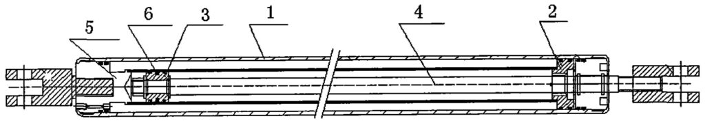
Detailed Implementation As shown in Figures 1 and 2, it includes a cylinder 1, rear seal 5, piston 3, guide sleeve 2, piston rod 4, and guide ring 6.
The end of the cylinder 1 is welded with a rear seal 5, and a piston 3 is installed inside the cylinder. The front end is welded with a guide sleeve 2, and the piston rod 4 passes through the guide sleeve 2 to connect to the piston 3.
Since the guide sleeve 2 and the rear seal 5 are welded to the cylinder 1, both bear half the pressure generated by the internal pressure of the cylinder 1. This type of sealed gas spring is difficult to withstand internal pressure, posing safety risks, making it challenging to manufacture heavy duty gas springs. Now, the outer walls of the guide sleeve 2 and the rear seal 5 are provided with external threads, and the inner wall of the cylinder 1 is provided with internal threads. The guide sleeve 2 and the rear seal 5 are connected to the cylinder 1 by internal and external threaded sliding fit and are welded to strengthen the connection, ensuring the safety of the gas spring.
Theoretically, there is a certain gap between the piston 3 and the inner wall of the cylinder 1, causing the piston 3 to scrape the inner wall of the cylinder 1 and the guide sleeve 2 during movement, leading to wear on the guide sleeve 2 or the piston rod 4. This problem is often overlooked in common gas spring design, as concentricity between the piston 3, piston rod 4, and the inner circle of the cylinder 1 is often ignored. As shown in Figure 2, a wear-resistant guide ring 6 is installed on the outer circumferential surface of the piston 3. The guide ring 6 supports the piston 3 and the piston rod 4 in the middle of the inner wall of the cylinder 1, ensuring the concentricity of the inner wall of the cylinder 1 with the piston 3 and the piston rod 4 during the movement of the gas spring, reducing wear on the guide sleeve 2 and the piston rod 4, and improving its service life.
Claims (4) – Super Heavy Duty Gas Spring with Reinforced Structure patent by LeiYan
- A super heavy duty Gas Spring with Reinforced Structure, comprising a cylinder, piston, and its piston rod. The end of the cylinder is welded with a rear seal, and a piston is installed inside the cylinder. The front end is welded with a guide sleeve through which the piston rod passes to connect to the piston. It is characterized by: the joints between the guide sleeve, rear seal, and the inner wall of the cylinder are connected first by threaded sliding fit and then welded or folded; the piston is equipped with a guide ring.
Auto-Reset Lockable Gas Spring
Patent No.:CN201198885 Date:2008-04-28
Google Patent: https://patents.google.com/patent/CN201198885Y/en?oq=CN201198885
China Patent: http://epub.cnipa.gov.cn/
Abstract
This utility model provides an auto-reset lockable gas spring, composed of a cylinder, piston, and rear plug. The floating piston inside the cylinder divides it into two chambers, filled with nitrogen and hydraulic oil respectively. In the chamber filled with hydraulic oil, the piston is sealed with an O-ring. The piston is connected to a piston rod, valve core assembly, and valve needle. A wide groove is created on the piston, with the O-ring situated in the groove, and a reset hole is also made on the piston. This design incorporates a reset hole in the piston of the gas spring, and through the coordination of the piston, reset hole, and O-ring, it not only achieves automatic resetting but also enables a slow and steady extension and resetting function due to the internal pressure of the gas spring when external force is lost. This function is applicable to any type of lockable gas spring.
Description
A Type of Auto-Reset Lockable Gas Spring
Technical Field The utility model relates to a gas spring, specifically a gas spring that can automatically reset and be lockable.
Background Technology Currently, the market offers various types of lockable gas springs, but they are limited to the locking adjustment function and cannot achieve automatic resetting. With the widespread application of gas springs, devices such as bus seats, airplane cabin seats, and other single gas, gas-oil mixed, and gas-oil separated types of equipment can all be designed for automatic resetting to enhance convenience. However, there has not been an auto-reset lockable spring that can meet these needs.
Utility Model Content This utility model provides an auto-reset lockable gas spring.
To solve the above technical problems, this utility model provides an auto-reset lockable gas spring, which consists of a cylinder, a piston, and a rear plug. Inside the cylinder is a floating piston that divides the cylinder into two chambers filled with nitrogen and liquid oil, respectively. In the chamber filled with hydraulic oil, the piston is sealed with an O-ring. The piston is connected to a piston rod, valve core assembly, and valve needle. The characteristic of this design is that the piston has a wide groove with an O-ring in it and a reset hole on the piston.
The width of the groove on the piston is twice the diameter of the O-ring.
The reset hole consists of a vertical hole and a horizontal hole.
The horizontal hole of the reset hole is located at the centerline of the groove width on the piston.
Advantages of the Structure: The innovation of this structure lies in adding a reset hole to the piston, and through the coordination of the piston, reset hole, and O-ring, it achieves automatic resetting. In the absence of external force, due to the internal pressure of the gas spring, it can achieve a slow return of gas in both chambers, slowly extending and resetting. This function is applicable to any type of lockable gas spring.
Description of Drawings
Figure 1 is a schematic diagram of the structure of this utility model.
Figure 2 is an enlarged view of the piston of this utility model.
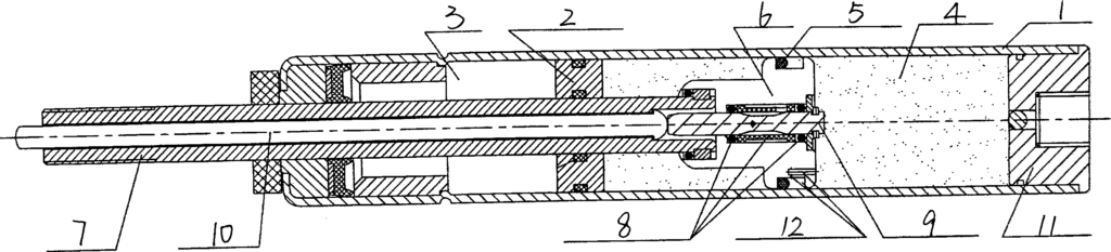
Detailed Implementation As shown in Figures 1 and 2, the bottom of the gas spring cylinder 1 is fixed with a rear plug 11, and inside it is a floating piston 2. The floating piston 2 divides the cylinder 1 into two chambers, filled with nitrogen 3 and liquid oil 4, respectively. In the chamber filled with hydraulic oil 4, the piston 6 is sealed with an O-ring 5. The piston 6 is connected to the valve core assembly 8, valve needle 9, piston rod 7, and the activation rod 10 on the piston rod 7. The main innovation of this structure lies in increasing the width of the groove 15 on the piston 6 to twice the diameter of the O-ring 5 and adding a reset hole 12 on the piston 6. The reset hole 12 consists of a vertical hole 13 and a horizontal hole 14, with the horizontal hole 14 located at the centerline of the groove width on the piston 6. The O-ring 5 moves up and down within the wide groove 15 on the piston 6 along the horizontal hole 14 of the reset hole 12, sealing as the lockable gas spring is compressed and extended. When the lockable gas spring is in a compressed state, the O-ring 5 floats to the upper end of the horizontal hole 14 of the reset hole 12 for sealing. During the extension adjustment, the O-ring 5 floats to the lower end of the horizontal hole 14 of the reset hole 12 for sealing. The compression and extension adjustment of this spring are the same as other lockable gas springs. The difference is that in the absence of external force, due to the internal pressure of the lockable gas spring, the O-ring 5 also floats to the lower end of the horizontal hole 14 of the reset hole 12, thus achieving the function of slowly returning gas in both chambers and slowly extending and resetting. This function is suitable for any type of lockable gas spring, including single gas, gas-oil mixed, gas-oil separated (including front separation and rear separation) types.
Claims (4) – Auto-Reset Lockable Gas Spring invented by LeiYan Gas Springs
- A Type of Auto-Reset Lockable Gas Spring, consisting of a cylinder, piston, and rear plug, with a floating piston built inside the cylinder. The floating piston divides the cylinder into two chambers filled with nitrogen and liquid oil respectively. In the chamber filled with hydraulic oil, the piston is sealed with an O-ring. The piston is connected to a piston rod, valve core assembly, and valve needle. It is characterized by: a wide groove on the piston, with the O-ring situated in the groove, and a reset hole on the piston.
- According to claim 1, the width of the groove on the piston is twice the diameter of the O-ring.
- According to claim 1, the reset hole consists of a vertical hole and a horizontal hole.
- According to claim 3, the horizontal hole of the reset hole is located at the centerline of the groove width on the piston.
A Gas Spring with a Stable Variable Resistance Groove
Patent No.:CN201202760 Date:2008-01-14
Google Patent: https://patents.google.com/patent/CN201202760Y/en?oq=CN201202760
China Patent: http://epub.cnipa.gov.cn/
A Gas Spring with a Stable Variable Resistance Groove
Abstract
This utility model provides a gas spring with a stable variable resistance groove. The piston is built inside the cylinder and is fixed together with the piston rod through riveting or screws. The piston rod and the cylinder are sealed together with a guiding and sealing system. The rectangular sealing ring and the cylinder with the stable variable resistance groove, along with the rear plug, are welded together to form a sealed gas spring cylinder. This gas spring has a damping groove on the tube wall of the gas spring. The depth of the damping groove can be varied according to different damping requirements, and it does not get clogged.
Description
A Gas Spring with a Stable Variable Resistance Groove
Technical Field The utility model relates to a gas spring, specifically a gas spring with a stable variable resistance groove.
Background Technology Gas springs are widely used in the automotive industry, but the magnitude of damping force and damping speed of gas springs have always been research and improvement topics. Currently, to achieve the desired gas spring rebound speed, various methods have been applied to the piston, such as using small apertures, small apertures with short damping grooves, small apertures with annular damping grooves and shims, or bidirectional labyrinth grooves with double shims. These methods aim to reduce the damping area and lengthen the damping channel. Although these methods can change the rebound speed of gas springs and achieve good results, they also have issues like clogging of small apertures and abnormal noise when gas and oil pass through.
Utility Model Content This utility model provides a gas spring with a stable variable resistance groove.
To solve the above technical problems, the gas spring with a stable variable resistance groove of this utility model includes a piston built inside the cylinder, fixed together with the piston rod through riveting or screws, and a guiding and sealing system sealing the connection between the piston rod and the cylinder. The rectangular sealing ring and the cylinder with the stable variable resistance groove, along with the rear plug, are welded together to form a sealed gas spring cylinder.
The stable variable resistance groove can have different shapes.
Advantages of the Structure: The gas spring has a damping groove on the gas spring tube wall. The damping groove can be made in different forms according to different damping requirements, such as uniform depth, gradually shallower, gradually deeper, or alternating shallow and deep. No matter the form, they share a common feature: the damping groove will not clog. The reason is that the piston of this gas spring only has venting or oil holes without passing damping holes; its damping is achieved through the damping groove on the tube wall. This design not only achieves the desired rebound speed but also addresses issues such as clogging of small apertures and abnormal noise when gas and oil pass through, providing a relatively stable constant speed effect through different forms of damping grooves.
Description of Drawings
Figure 1 is a schematic diagram of the structure of this utility model.
Figure 2 is a schematic diagram of the variable resistance groove from shallow to deep and then to deep.
Figure 3 is a schematic diagram of the variable resistance groove from shallow to deep.
Detailed Implementation As shown in Figure 1, the piston 6 is built inside the cylinder and fixed together with the piston rod 1 through riveting or screws. The piston rod 1 and the cylinder are sealed together with a guiding and sealing system 2. The rectangular sealing ring 3 and the cylinder with the stable variable resistance groove 4, along with the rear plug 5, are welded together to form a sealed gas spring cylinder. As shown in Figures 2 and 3, the variable resistance groove can be of uniform depth, gradually shallower, gradually deeper, or alternating shallow and deep as needed. When the gas spring moves, the rectangular sealing ring 3, under pressure, tightly adheres to the inner wall of the cylinder with the stable variable resistance groove 4, sealing the other parts except for the damping groove. During the movement, the rectangular sealing ring 3 and the cylinder with the stable variable resistance groove 4 provide damping while opening, preventing any clogging. If a damping groove from shallow to deep is used, the rebound speed of the gas spring will approximate a constant speed, as the rebound speed of the gas spring is related to internal pressure and the cross-sectional area of the damping groove. When the piston rod extends, the internal pressure decreases, and the cross-sectional area of the damping groove increases, complementing each other to produce a relatively stable rebound speed.
Claims (2) – A Gas Spring with a Stable Variable Resistance Groove applied on dynamic damping gas spring invented by LeiYan Gas Springs.
1、A Gas Spring with a Stable Variable Resistance Groove, wherein the piston is built inside the cylinder and fixed together with the piston rod through riveting or screws, and the piston rod and the cylinder are sealed together with a guiding and sealing system; it is characterized by: the rectangular sealing ring, the cylinder with the stable variable resistance groove, and the rear plug are welded together to form a sealed gas spring cylinder.