Tag: leiyan gas spring patent
forced mechanical locking gas spring
Patent No.:CN101487507 Date:2008-01-14
Google Patent: https://patents.google.com/patent/CN101487507A/en?oq=CN101487507
China Patent: http://epub.cnipa.gov.cn/
Abstract
This invention provides a type of forced mechanical locking gas spring, including a gas spring cylinder, a built-in piston inside the cylinder, a piston rod riveted to the piston, a guiding and sealing system, and a front connector attached to the piston rod, with a locking sleeve and a return spring attached to the front connector. The wrench bracket is welded onto the locking sleeve, and the strong locking wrench is installed on the wrench bracket. By adopting the two components of the wrench bracket and the strong locking wrench, it not only relies on the locking sleeve’s offset to support the lock but also has a strong locking wrench for forced locking, thereby doubling the safety factor during use. It is suitable for environments where malfunctions easily occur, such as facilities and equipment, and is also applicable in other fields such as sports equipment and treadmills.
Description
A Type of Forced Mechanical Locking Gas Spring
Technical Field The invention relates to a gas spring, specifically a type of forced mechanical locking gas spring.
Background Technology Gas springs are considered safety components abroad and have their own integrity requirements. In practical applications, there is an increasing focus on safety. In this context, using gas springs as mechanical locking devices has become more common. The current market’s locking devices rely solely on the offset of the locking sleeve to support the lock, which is unsuitable for environments prone to operational errors.
Summary of the Invention This invention provides a type of forced mechanical locking gas spring with double safety assurance.
To solve the above technical problems, the forced mechanical locking gas spring of this invention includes a gas spring cylinder, a built-in piston inside the cylinder, a piston rod riveted to the piston, a guiding and sealing system, and a front connector attached to the piston rod, with a locking sleeve and a return spring attached to the front connector. The wrench bracket is welded onto the locking sleeve, and the strong locking wrench is installed on the wrench bracket.
The strong locking wrench’s locking part is in the shape of an eccentric wheel and can be turned 180°.
The advantage of this structure is that it utilizes the two components of the wrench bracket and the strong locking wrench. It not only relies on the locking sleeve’s offset to support the lock but also has a strong locking wrench for forced locking, thus doubling the safety factor during use. It is suitable for environments where operational errors are likely, such as facilities and equipment, and is also applicable in other fields such as sports equipment and treadmills.
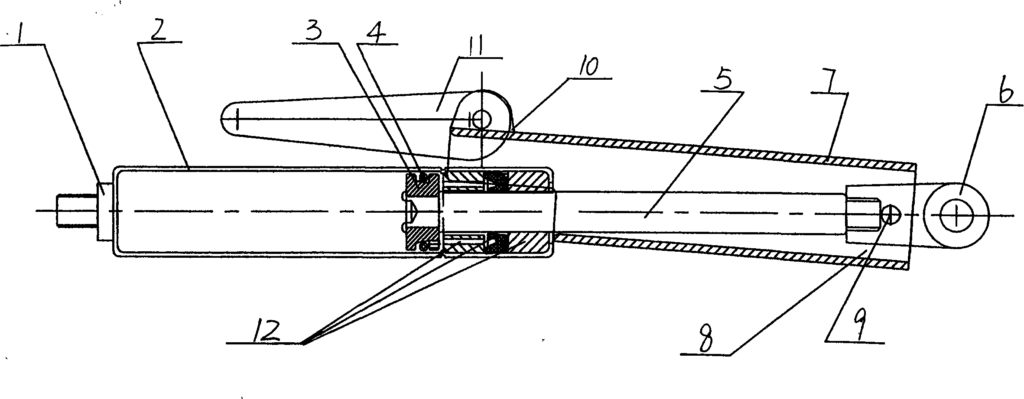
Description of the Drawings The figure is a schematic diagram of the structure of the invention.
Detailed Implementation As shown in the figure, the rear plug 1 and the cylinder 2 are welded into a sealed gas spring cylinder. The piston 3 and the O-ring 4 form a complete piston, with a guiding and sealing system 12 for guiding and sealing at this location. The piston is riveted to the piston rod 5. The front connector 6 is attached to the piston rod 5. The locking sleeve 7 and the return spring 8 are connected to the front connector 6 by the locking sleeve bolt 9. The wrench bracket 10 is welded onto the locking sleeve 7, and the strong locking wrench 11 is installed on the wrench bracket 10. The strong locking wrench 11’s locking part is shaped like an eccentric wheel and can be turned 180° to achieve the functions of strong locking and unlocking.
In operation, taking the maintenance of a large and heavy machine door as an example, the machine door needs to be opened and kept open for a long time during maintenance. At this time, the gas spring’s function is to open and support. The ordinary locking support component on the gas spring relies on the small force of the return spring 8 for the locking sleeve 7’s offset, achieving the purpose of support and locking, but it cannot prevent accidents. In this case, the wrench bracket 10 welded onto the locking sleeve 7 applies force to the strong locking wrench 11, which turns 180° like an eccentric wheel, initiating the strong lock function, thereby achieving dual mechanical locking and reducing safety risks.
Claims (2) – forced mechanical locking gas spring patent by LeiYan
- A Type of Forced Mechanical Locking Gas Spring, including a gas spring cylinder, a built-in piston inside the cylinder, a piston rod riveted to the piston, a guiding and sealing system, and a front connector attached to the piston rod with a locking sleeve and return spring attached to the front connector. It is characterized by: the wrench bracket being welded onto the locking sleeve, and the strong locking wrench being installed on the wrench bracket.
- According to claim 1, the strong locking wrench’s locking part is in the shape of an eccentric wheel and can be turned 180°.
Gas spring with variable force value and circulating and reversible rotation angle
Patent No.:CN101487482 Date:2008-01-14
Google Patent: https://patents.google.com/patent/CN101487482A/en?oq=CN101487482
China Patent: http://epub.cnipa.gov.cn/
Abstract
The invention provides a force changeable, cyclic and reversible angular motion gas spring. A cylinder body and a rear sealing pressure regulating system are weld together to form an enclosed gas spring cylinder body, an O-shaped ring and a directional floating piston are combined with a positioning convex groove of the cylinder body to generate friction force for an angular shaft under the action of power source nitrogen gas, meanwhile, the volume of a gas chamber is changed by the rear sealing pressure regulating system to change the value of the friction force, thus realizing cyclic and reversible motion and angular motion. The rotation friction force of the novel gas spring is changeable and adjustable, and an adjustment angle is cyclic and reversible, which can realize unlimited adjustment of a cyclic angle and can realize fixed value adjustment of the cyclic angle, and meets requirements of a certain emerging and specific products and industries.
Description
A kind of gas spring with variable force value and circulating and reversible rotation angle
Technical field
The present invention relates to a kind of air spring, particularly a kind of gas spring with variable force value and circulating and reversible rotation angle.
Background technique
The pattern of air spring motion in the past is the single pressure stretch motion of contracting, and the air spring of the type is owing to function singleness, application is limited, can not satisfy for example medical apparatus angle adjustment especially, computer monitor, TV-set carriage angle adjustment or the like some emerging certain products and industries.
Summary of the invention
The invention provides a kind of gas spring with variable force value and circulating and reversible rotation angle.
In order to solve above technical problem, a kind of gas spring with variable force value and circulating and reversible rotation angle of the present invention, forming built-in directed floating piston in smooth rotation output unit, cylinder body, the cylinder body, power source and back envelope voltage-regulating system by the advancing slip pearl in corner axle and the cylinder body forms, described cylinder body welds together with back envelope voltage-regulating system forms airtight air spring cylinder body, described directed floating piston in the air spring cylinder body, is the power source region with O type ring seal device between described directed floating piston and back envelope voltage-regulating system.
Described corner shaft rear end can be that cone also can be the plane.
When described corner shaft rear end is the plane, the corner positioning bead is installed on this plane.
Described directed floating piston front can be that taper hole also can be the plane.
When described directed floating piston front was the plane, a basic circle had been established many equal angles in this upper edge, plane, symmetrical pit.
The advantage of above structure is: this gas spring with variable force value and circulating and reversible rotation angle welds together with back envelope voltage-regulating system by cylinder body forms airtight air spring cylinder body, O type circle and directed floating piston, in conjunction with the location tongue of cylinder body under the effect of power source nitrogen, the corner axle is produced frictional force, and change the size of frictional force simultaneously by the volume of back envelope regulating system change air cavity.Realize that like this circulating and reversible rotates, the corner motion, and this novel air spring rotation friction variable adjustable, and the angle modulation circulating and reversible.Can realize that not only cycle perspective is infinitely adjustable, can also realize that the cycle perspective definite value is adjustable.Its appearance will have been satisfied some emerging certain products and industries.It can be widely used in some occasion work light illumination direction adjusting etc.
Description of drawings
Fig. 1 is the structural representation of the embodiment of the invention 1;
Fig. 2 is the structural representation of the embodiment of the invention 2.
Embodiment
Specific embodiment 1:
As shown in Figure 1, the rear end of corner axle 1 is a cone, form smooth rotation output with advancing slip pearl 3, cylinder body 2 welds together with back envelope voltage-regulating system 7 forms airtight air spring cylinder body, there is the directed floating piston 5 of taper hole O type circle 4 and front, under the effect of power source nitrogen 6, the awl end of corner axle 1 is produced frictional force in conjunction with the location tongue of cylinder body 2, back envelope regulating system 7 is the sizes that change frictional force by the volume that changes air cavity.Selecting corner axle 1 and directed floating piston 5 to be the tapered sleeve friction type in Fig. 1, is in order to strengthen the effect of frictional engagement face stable center.It is applicable on the apparatus of any change angle.
Specific embodiment 2:
As shown in Figure 2, corner axle 1 is formed smooth rotation output with advancing slip pearl 3, different is with corner axle among Fig. 11, corner axle 1 rear end is not that cone is the plane among Fig. 2, corner positioning bead 8 is just installed on this plane, cylinder body 2 welds together with back envelope voltage-regulating system 7 forms airtight air spring cylinder body, O type circle 4 is contained on the directed floating piston 5, different is that directed floating piston 5 fronts have been not taper holes, be the plane and processed many equal angles along certain circle, the symmetry pit, in conjunction with the location tongue of cylinder body 2 under the effect of power source nitrogen 6, corner axle 1 ear end face is implemented thrust, and corner positioning bead 8 at this moment just should drop on the front-end face of directed floating piston 5 in the symmetrical grooves, and corner power size is born object gravity+outer active force.Back envelope regulating system 7 is the sizes that change thrust or corner power by the volume that changes air cavity.It is applicable to the air spring of this circulating and reversible angle of Fig. 2 definite value adjustable structure on the apparatus of definite value angle modulation.
Claims (5)
Hide Dependent
- gas spring with variable force value and circulating and reversible rotation angle, form built-in directed floating piston in smooth rotation output unit, cylinder body, the cylinder body, power source and back envelope voltage-regulating system by the advancing slip pearl in corner axle and the cylinder body and form, it is characterized in that: described cylinder body welds together with back envelope voltage-regulating system forms airtight air spring cylinder body; Described directed floating piston in the air spring cylinder body, is provided with the power source region with O type ring seal device between described directed floating piston and back envelope voltage-regulating system.
- a kind of gas spring with variable force value and circulating and reversible rotation angle according to claim 1 is characterized in that: described corner shaft rear end can be that cone also can be the plane.
- a kind of gas spring with variable force value and circulating and reversible rotation angle according to claim 2 is characterized in that: when described corner shaft rear end is the plane, the corner positioning bead is installed on this plane.
- a kind of gas spring with variable force value and circulating and reversible rotation angle according to claim 1 is characterized in that: described directed floating piston front can be that taper hole also can be the plane.
- a kind of gas spring with variable force value and circulating and reversible rotation angle according to claim 4 is characterized in that: when described directed floating piston front was the plane, a basic circle had been established many equal angles in this upper edge, plane, symmetrical pit.
Claims (5) patent gas spring with variable force value and circulating and reversible rotation angle
1. gas spring with variable force value and circulating and reversible rotation angle, form built-in directed floating piston in smooth rotation output unit, cylinder body, the cylinder body, power source and back envelope voltage-regulating system by the advancing slip pearl in corner axle and the cylinder body and form, it is characterized in that: described cylinder body welds together with back envelope voltage-regulating system forms airtight air spring cylinder body; Described directed floating piston in the air spring cylinder body, is provided with the power source region with O type ring seal device between described directed floating piston and back envelope voltage-regulating system.
2. a kind of gas spring with variable force value and circulating and reversible rotation angle according to claim 1 is characterized in that: described corner shaft rear end can be that cone also can be the plane.
3. a kind of gas spring with variable force value and circulating and reversible rotation angle according to claim 2 is characterized in that: when described corner shaft rear end is the plane, the corner positioning bead is installed on this plane.
4. a kind of gas spring with variable force value and circulating and reversible rotation angle according to claim 1 is characterized in that: described directed floating piston front can be that taper hole also can be the plane.
5. a kind of gas spring with variable force value and circulating and reversible rotation angle according to claim 4 is characterized in that: when described directed floating piston front was the plane, a basic circle had been established many equal angles in this upper edge, plane, symmetrical pit.
Gas spring capable of adjusting relief pressure
Patent No.:CN201202761 Date:2008-01-14
Google Patent: https://patents.google.com/patent/CN201202761Y/en?oq=CN201202761
China Patent: http://epub.cnipa.gov.cn/
Abstract
The utility model provides an adjustable pressure relief gas spring which is composed of a gas spring cylinder body, a piston and a piston rod riveted with the piston; the cylinder body is welded with a back seal together to construct an airtight gas spring cylinder body; a pressure relief hole and a work position used for mounting the pressure relief part are arranged on the back seal; a seal piece is mounted on the bottom part of the back seal pressure relief work position; a gasket is pressed on the seal piece. The gas spring which adopts the structure to realize the pressure relief adjustment through adjusting the pressure relief screw outwards after the pneumatic is once mounted; thereby, the best application effect is realized through adjustment after the pneumatic is once mounted; the assembly and disassembly of the gas spring are convenient.
Description
A kind of can regulate is rushed down push-type gas spring
Technical field
The utility model relates to a kind of air spring, and particularly a kind of can regulate is rushed down push-type gas spring.
Background technique
The perfection of air spring performance, the increase of function is to change along with client’s demands of applications.Sometimes air spring is on some product or apparatus, the installing/dismounting inconvenience, do not have a kind of can be once good and sound after again through adjusting the air spring that just can reach best using effect.
The model utility content
The utility model provides a kind of can regulate to rush down push-type gas spring.
In order to solve above technical problem, a kind of can regulate of the present utility model is rushed down push-type gas spring, reaching the piston rod of riveting with piston by air spring cylinder body, piston forms, described cylinder body is connected together with back soldering and sealing and forms airtight air spring cylinder body, after seal up to rush down and press the hole and the station that rushes down pressure part is installed, Sealing is contained in the back envelope and rushes down the bottom of pressing station, and pad is pressed on the Sealing.
Described pad seals riveting with the back, rushes down and press the screw front end to be the needle shape, and two small blind holes are anyhow arranged.
Described by pad, seal ring, rush down press that screw forms rush down pressure part can after seal up horizontal assembling, also can vertically assemble at the ear end face that the back is sealed.
The advantage of the above structure of the utility model is: adopt air spring on some product or apparatus, sometimes installing/dismounting inconvenience, for make air spring in use can be once good and sound after again through adjusting the using effect that just can reach the best, the utility model is taked to be connected together in air spring cylinder body and back soldering and sealing and is formed airtight air spring cylinder body, after seal up to rush down and press the hole and the station that rushes down pressure part is installed, Sealing is contained in the back envelope and rushes down the bottom of pressing station, pad is pressed in the structure on the Sealing, and make bearing pressure F1 or pressure F3 15-25% greater than normal use value, press the screw realization adjustable by slowly outwards regulating to rush down, thereby reach once good and sound again through adjusting the using effect that just can reach best.
Description of drawings
Figure is a structural representation of the present utility model.
Embodiment
As shown in the figure, Sealing 6 is installed on the piston 1, piston 1 and piston rod 2 are riveted together, between piston rod 2 and cylinder body 3, be provided with sealing guidance system 9, and cylinder body 3 welds together with back envelope 4 and form airtight air spring cylinder body, be processed with on the back envelope 4 to rush down and press the hole and the station that rushes down pressure part is installed, Sealing 7 is contained in back envelope 4 and rushes down the bottom of pressing station, pad 5 is pressed on the Sealing 7, and with back envelope 4 rivetings, rush down and press screw 8 front ends to be the needle shape, and two small blind holes are anyhow arranged.
When air spring rushes down the realization of pressing performance, the bearing pressure F1 of product or pressure F3 should be greater than the 15-25% of normal use value, slowly outwards regulate to rush down after installing and press screw 8, the sealing center line that little cross-drilled hole withdraws from Sealing 7 on the needle shape just begins to rush down pressure, inwardly regulate to rush down rapidly when rushing down and press screw 8, it is closed rush down pressure to suitable power value.
The above-described this laminated structure that rushes down is not limited only to laterally assembling on back envelope 4, also can vertically assemble at the ear end face of back envelope 4.
Claims (3) – patented gas spring capable of adjusting relief pressure
1, a kind of can regulate is rushed down push-type gas spring, reaching the piston rod of riveting with piston by air spring cylinder body, piston forms, it is characterized in that: described cylinder body is connected together with back soldering and sealing and forms airtight air spring cylinder body, after seal up to rush down and press the hole and the station that rushes down pressure part is installed, Sealing is contained in the back envelope and rushes down the bottom of pressing station, and pad is pressed on the Sealing.
2, a kind of can regulate according to claim 1 is rushed down push-type gas spring, it is characterized in that: described pad seals riveting with the back, rushes down and press the screw front end to be the needle shape, and two small blind holes are anyhow arranged.
3, a kind of can regulate according to claim 1 is rushed down push-type gas spring, it is characterized in that: described by pad, seal ring, rush down press that screw forms rush down pressure part can after seal up horizontal assembling, also can vertically assemble at the ear end face that the back is sealed.
Simple corner door closer
Patent No.:CN2584760 Date:2002-10-25
Google Patent: https://patents.google.com/patent/CN2584760Y/en?oq=CN2584760
China Patent: http://epub.cnipa.gov.cn/
Abstract
The utility model discloses a simple corner door closer, which comprises a reset pull rod, a gas spring, and a shell. The simple corner door closer is characterized in that upper and lower cavities are arranged in the shell; the upper and the lower cavities are vertically and horizontally staggered perpendicularly; a corner gear is arranged in the upper cavity, and is connected with the reset pull rod; the lower cavity is provided with a rack which is engaged with the corner gear; the rack is connected with the gas spring by an expansion rod; the gas spring adopts a separate type gas spring. The outer end of the gas spring and the lower cavity of the shell of the simple corner door closer are in screw connection; the reset pull rod adopts a floating type reset pull rod. The simple corner door closer has the advantages of simple structure, long service life, low cost, and convenient installation. The utility model may use a micro gas spring to solves the problem that doors are closed at any time in winter in north, and is suitable for air conditioning rooms, toilets, and kitchens.
Description
Simple and easy corner door closer
Technical field
The utility model relates to a kind of corner door closer.
Background technology
The thrust unit formation that the door closer of known technology generally comprises pull bar, is connected with pull bar; Its pull bar thrust unit has the employing vapour-pressure type, as application number is 00239985, the applying date is on November 3rd, 2000, denomination of invention is the disclosed technology of the patent of vapour-pressure type door closer, this vapour-pressure type door closer comprises cavity, be positioned at the pull bar of cavity inner chamber, the piston sheet, two piston sheets are installed in the pull bar front end back-to-back, the cross section of piston sheet is basin shape, on two piston sheets the pore that communicates is arranged, between two piston sheets rubber ring is housed, cavity inner chamber front end has three grades of through holes, screw cooperates with screwed hole in three grades of through holes, control turnover tolerance makes door closer switch door adjustable-speed.Though above-mentioned door closer volume is little, the action of closing the door is soft, complex structure, it is many to produce failure factor, thereby application life is limited, and cost is also higher, and comparatively trouble is installed also.
Summary of the invention
The purpose of this utility model is to provide a kind of simple in structure, long service life, cost simple and easy corner door closer low, easy for installation.
For achieving the above object, the utility model is to adopt following scheme to realize: this door closer comprises reset lever, air spring, housing, be provided with cavity up and down in the housing, cavity vertical interlaced in length and breadth up and down, be provided with the corner gear in the upper plenum, the corner gear is connected with reset lever, and following cavity is provided with tooth bar, tooth bar and the interlock of corner gear, tooth bar is connected by expansion link with air spring.
As the further improvement of such scheme, air spring of the present utility model adopts the separate type air spring.Adopt between cavity under its outer end and the door closer housing and be threaded.
Above-mentioned reset lever adopts floating type reset lever.
Adopt the beneficial effect of said structure to be, the utility model only is made up of power source (being air spring power), tooth bar, corner gear, housing, release link, it designs unique, have following characteristics: 1, power has partly adopted the separate type air spring, assembling and regular maintenance are flexible, therefore the design F1 of air spring power, F2 ratio are similar to 1 ≈ 1, and it is steady, soft to produce torsion, have reduced the noise when closing; Adopt floating type release link to make user installation easy when 2, closing, need not to consider strict installation site and size, a surface is damaged; Whether it can be provided with to open when door 90 is spent suspends, make the user arbitrarily determine through normal closed gate; 3, this kind door closer part accessory is few, the part localization rate of parts and components reaches 100%, life-span is long, close Men Keda 3.5 ten thousand times, lower than other door closer cost of existing use, price is low, it had both solved the problem that north of china in winter will be closed the door at any time, more be adapted to air-conditioned room, washroom, kitchen are the desirable good products that can be accepted by huge numbers of families.
Description of drawings
Be described further below in conjunction with drawings and Examples;
Fig. 1 is the utility model broken section structural representation;
Fig. 2 looks up direction broken section structural representation for Fig. 1;
Fig. 3 is Fig. 1 left view.
The specific embodiment
As Fig. 1~shown in Figure 3, door closer of the present utility model comprises floating type reset lever (1), air spring (8), housing (2); Be provided with upper plenum (6), following cavity (5) in the housing (2), cavity vertical interlaced in length and breadth up and down, be provided with corner gear (3) in the upper plenum (6), corner gear (3) is fixedlyed connected with reset lever (1), following cavity (5) is provided with tooth bar (4), tooth bar (4) and corner gear (3) interlock, tooth bar (4) is connected by expansion link (7) with separate type air spring (8).Adopt between cavity (5) under air spring (8) outer end and the door closer housing to be threaded, install more convenient; Also be provided with fixing threaded hole (9) on the housing.
Claims (4)
1. simple and easy corner door closer, comprise reset lever, air spring, housing, it is characterized in that, be provided with up and down cavity in the housing, cavity vertical interlaced in length and breadth is provided with the corner gear in the upper plenum up and down, the corner gear is connected with reset lever, following cavity is provided with tooth bar, tooth bar and the interlock of corner gear, and tooth bar is connected by expansion link with air spring.
2. simple and easy corner door closer according to claim 1 is characterized in that, described air spring adopts the separate type air spring.
3. simple and easy corner door closer according to claim 1 is characterized in that, adopts between cavity under the outer end of described air spring and the door closer housing to be threaded.
4. simple and easy corner door closer according to claim 1 is characterized in that described reset lever adopts floating type reset lever.