Tag: lockable gas spring
Terms, Definitions of lockable gas spring
3. Terms, Definitions, Symbols, and Explanations
The terms, definitions, symbols, and explanations established in GB/T 1805 and Table 1 apply to this standard.
| Term | Definition or Explanation | Symbol | Unit |
| Gas spring | An elastic element composed of a sealed cylinder barrel, a piston that can slide inside the cylinder barrel, and a piston rod assembly, using nitrogen or other inert gases as the energy – storage medium. Note: Adapted from GB/T 1805—2001, Definition 2.9 | ||
| Lockable gas spring | A gas spring that can be locked or unlocked at any position within its movement stroke | ||
| Piston rod diameter | The diameter of the piston rod of a gas spring [GB/T 1805—2001, Definition 3.111] | d | mm |
| Cylinder inner diameter | The inner diameter of the cylinder barrel of a gas spring | D1 | mm |
| Cylinder outer diameter | The outer diameter of the cylinder barrel of a gas spring [GB/T 1805—2001, Definition 3.110] | D2 | mm |
| Stroke | The axial displacement of the piston rod from the fully extended state to the state when compressed to the minimum size | S | mm |
| Extended length | The effective length of a gas spring in the fully extended state | L | mm |
| Unlocking force | The force required to release the locked state of a gas spring and open the valve | Fk | N |
| Start – up force | The initial force required to press the piston rod after opening the valve, when the gas spring has been in the extended state for a certain period of time [GB/T 1805—2001, Definition 3.116] | F0 | N |
| One cycle | The piston rod is compressed and extended once each according to the specified stroke | ||
| Extension speed | The average speed at which the piston rod freely extends from the end of the specified stroke to the initial position | v – | mm/s |
| Specified force | The force marked on the product drawings and products confirmed by both the supplier and the demander (F1, Fa, F3, …) | F× | N |
| Minimum extension force | The force measured at the specified force – taking point C near the starting point of the working stroke during the extension process. Note: Adapted from GB/T 1805—2001, Definition 3.119 | F1 | N |
| Maximum extension force | The force measured at the specified force – taking point C near the end point of the working stroke during the extension process. Note: Adapted from GB/T 1805—2001, Definition 3.120 | F2 | N |
| Minimum compression force | The force measured at the specified force – taking point C near the starting point of the working stroke during the compression process. Note: Adapted from GB/T 1805—2001, Definition 3.121 | F3 | N |
| Maximum compression force | The force measured at the specified force – taking point C near the end point of the working stroke during the compression process. Note: Adapted from GB/T 1805—2001, Definition 3.122 | F4 | N |
| Nominal force a | One of the comprehensive characteristic indicators of a gas spring. It is the average value of the maximum extension force and the minimum compression force, i.e., Fa=(F1 + F3)/2. Note: Adapted from GB/T 1805—2001, Definition 3.123 | Fa | N |
| Nominal force b | The average value of the minimum extension force and the maximum compression force, i.e., Fb=(F2 + F4)/2. Nominal force b is generally used for calculating the force ratio | Fb | N |
| Dynamic friction force | The average value of the difference between the minimum compression force and the minimum extension force, i.e., Fr=(F3 – F1)/2. Note: Adapted from GB/T 1805—2001, Definition 3.124 | Fr | N |
| Force ratio | The ratio of nominal force b to nominal force a, i.e., α = Fb/Fa. Note: Adapted from GB/T 1805—2001, Definition 3.125 | α | |
| Rigid locking | In the locked state, when a gas spring is under the action of axial compression and tension forces, the piston rod generates displacement, and its force – displacement characteristic curve is as follows. | ||
| Elastic locking | In the locked state, when the displacement of the piston rod of a gas spring under the action of compression or tension forces is not more than 2mm, it can reach the agreed locking force (see Curves I and II). In the locked state, when the piston rod of a gas spring under the action of compression or tension forces generates a relatively large displacement (see Curve III) | ||
| Locking force | The axial compression or tension force required to cause a certain displacement of the piston rod when the gas spring is in the locked state | Fs | N |
| Force – taking point | The point for collecting force values during dynamic or static testing | C | mm |
Technical Specification for Lockable Gas Springs (English version of national strandard, initiated by LeiYan Gas Springs), proposed and prepared by SAC/TC 235 (National Technical Committee 235 on Spring of Standardization Administration of China).
Technical Specifications for Lockable Gas Spring
Lockable Gas Springs
1. Scope
This standard specifies the terms and definitions, markings, technical requirements, test methods, inspection rules, as well as the requirements for identification, packaging, transportation, and storage of lockable gas springs (hereinafter referred to as “gas springs”).
This standard is applicable to angle – adjustable lockable gas springs and other forms of lockable gas springs except for seat – lifting lockable gas springs, which use nitrogen or other inert gases as the energy – storage working medium.
Seat – lifting lockable gas springs are not applicable to this standard.
2. Normative Referenced Documents
The provisions of the following documents are incorporated into this standard by reference. For dated references, subsequent amendments (excluding corrigenda) or revised editions do not apply to this standard. However, parties to agreements based on this standard are encouraged to investigate the possibility of applying the latest versions of these documents. For undated references, the latest version applies to this standard.
- GB/T 1771 Paints and varnishes – Determination of resistance to neutral salt spray (GB/T 1771—2007, ISO 7253:1996, IDT)
- GB/T 1800.1 Geometrical product specifications (GPS) – Limits and fits – Part 1: Bases of tolerances, deviations and fits (GB/T 1800.1—2009, ISO 286 – 1:1988, MOD)
- GB/T 1805 Spring terms
- GB/T 2348 Hydraulic fluid power systems and components – Cylinder bores and piston rod diameters (GB/T 2348—1993, neq ISO 3320:1987)
- GB/T 2349 Hydraulic fluid power systems and components – Cylinder piston stroke series
- GB/T 2828.1 Sampling procedures for inspection by attributes – Part 1: Sampling schemes indexed by acceptance quality limit (AQL) for lot – by – lot inspection (GB/T 2828.1—2003, ISO 2859 – 1:1999, IDT)
- GB/T 2829 Sampling procedures and tables for inspection by attributes for periodic inspection of stability of processes
- GB/T 10125 Corrosion tests in artificial atmospheres – Salt spray tests (GB/T 10125—1997, eqv ISO 9227:1990)
- QC/T 484 Automotive paint coatings
- QC/T 625 Coatings and chemical treatment layers for automobiles
Technical Specification for Lockable Gas Springs (English version of national strandard, initiated by LeiYan Gas Springs), proposed and prepared by SAC/TC 235 (National Technical Committee 235 on Spring of Standardization Administration of China).
A Lockable Valve Body Piston Device with Altered Performance
Patent No.:CN113007258A Date:2021-04-27
Google Patent: https://patents.google.com/patent/CN113007258A/en?oq=CN113007258A
China Patent: http://epub.cnipa.gov.cn/
A Lockable Valve Body Piston Device with Altered Performance
Abstract
The present invention provides a lockable valve body piston device with altered performance. The device comprises a closed cavity, a piston assembly and a valve core assembly. The piston assembly includes a piston rod, a piston body and a seal. The piston body consists of a connecting part and a shaft shoulder part that are integrally connected. The shaft shoulder part is provided with a plurality of flow-through holes, extension damping holes and a plurality of compression flow-through holes. By means of the seal that is displaced by friction, the compression flow-through holes can be closed or opened to achieve the function of switching the flow rate of gas or medium oil. At the same time, the requirements of extension and compression movements are met, resulting in beneficial effects such as stable spring speed, stable working state, high safety and long service life. This solves the problem in the prior art that when adjusting the damping hole diameter, the design requirements of both extension and compression movements cannot be satisfied simultaneously, causing inconvenience in use, unstable working state, poor safety performance, and greatly reducing the consistency, smoothness and service life of the product.
Description
A Lockable Valve Body Piston Device with Altered Performance
Technical Field
The present invention relates to the field of gas springs, and specifically to a lockable valve body piston device with altered performance.
Background Art
A gas spring is a component capable of achieving functions such as support, buffering, braking, height and angle adjustment. In construction machinery, it is mainly applied to parts such as covers and doors. A gas spring mainly consists of a piston rod, a piston, a sealing guide sleeve, filling materials, a pressure cylinder, connectors, etc. The pressure cylinder is a closed cavity, filled with inert gas or an oil-gas mixture inside, and the pressure in the cavity is several times or dozens of times that of the atmospheric pressure.
When the valve body piston of a traditional gas spring undergoes extension or compression movement, the power gas or medium oil in the gas spring cylinder flows through the same damping hole. Its motion characteristics have at least the following problems:
- When the damping hole diameter is small, the damping force is relatively large, which meets the spring speed requirement of the piston’s extension movement speed. However, the compression movement will be relatively difficult, making the implementation of the compression movement difficult and inconvenient to use.
- When the damping hole diameter is large, the damping force is relatively small, which makes the compression movement easier. But the spring speed of the extension movement cannot be well damped and controlled, resulting in an unstable working state, poor safety performance, and greatly reducing the consistency, smoothness, and service life of the product.
Summary of the Invention
In view of this, the present invention provides a lockable valve body piston device with altered performance, which can solve at least one of the above problems. By means of a seal that is displaced by friction, the compression flow – through holes can be closed or opened to switch the flow rate of gas or medium oil. The piston assembly has good damping force during both extension and compression movements, achieving a good buffering effect, smooth movement, and at the same time improving safety and service life. The structure is simple, easy to manufacture, and has broad application prospects.
To achieve the above – mentioned objectives, the present invention provides the following technical solutions: A lockable valve body piston device with altered performance includes a closed cavity, a piston assembly and a valve core assembly arranged in the closed cavity. The piston assembly includes a piston rod, a piston body arranged on the piston rod, and a seal arranged on the piston body. The piston body includes a connecting part connected to the piston rod and a shaft shoulder part. The shaft shoulder part is provided with a plurality of flow – through holes, extension damping holes, and compression flow – through holes. The seal is displaced by friction to close or open the compression flow – through holes.
In some preferred embodiments, the flow – through holes are straight through – holes.
In some preferred embodiments, the flow – through holes are inclined through – holes.
In some preferred embodiments, a plurality of the flow – through holes are evenly distributed on the end face of the shaft shoulder part. A groove for placing the seal is provided on the side surface of the shaft shoulder part, and the groove is in communication with the flow – through holes, the extension damping holes, and the compression flow – through holes.
In some preferred embodiments, the groove includes a first groove and a second groove. The seal includes a first seal and a second seal. The first seal is placed in the first groove, and the second seal is placed in the second groove.
In some preferred embodiments, the depth of the groove opening on the side of the first groove close to the compression flow – through holes is consistent, and the depth of the groove opening at the end close to the extension damping holes gradually increases.
In some preferred embodiments, a valve core hole for installing the valve core assembly is provided on the shaft shoulder part.
In some preferred embodiments, a snap – fit structure adapted to the structure of the connecting end of the piston rod is provided on the connecting part.
In some preferred embodiments, the number of the extension damping holes is one.
In some preferred embodiments, the number of the flow – through holes is greater than or equal to the number of the compression flow – through holes.
Characteristics and Advantages of the Present Invention
- When the present invention undergoes compression movement, all the compression flow – through holes are opened by the friction – displaceable seal. The power – source gas or medium oil flows out through a plurality of compression flow – through holes, damping holes, and multiple flow – through holes. The transmission flow rate is greatly increased, making the compression movement easier, convenient to use, and highly efficient.
- When the present invention undergoes extension movement, the friction – displaceable seal blocks all the compression flow – through holes. At this time, the release of the power – source gas or medium oil can only flow through a plurality of flow – through holes and then through a single extension damping hole. By changing the size of the extension damping hole, it is only necessary to fully meet the spring speed requirement of the extension movement without considering the implementation of the compression movement. Thus, beneficial effects such as stable spring speed, stable working state, high safety, and long service life are achieved, solving the problem that has plagued lockable gas springs at home and abroad for many years.
- By changing the number of compression flow – through holes and through – holes to meet the maximum flow rate of gas or medium oil when the valve core is in the open state, the structure is simple, easy to manufacture, and has broad application prospects.
- The co – existence design of the inclined groove bottom of the groove at one end close to the extension damping hole and the flat groove bottom of the groove at one end close to the compression flow – through holes is beneficial to the closing or opening of the compression air flow holes, which is convenient to use and ingeniously designed.
- By designing a plurality of flow – through holes as straight through – holes or inclined through – holes, the actual volume and size requirements of the present invention are met, which is convenient to use and has broad application prospects.
Description of the Drawings
The following drawings are provided to further understand the present application, and they form a part of the present application. They are only intended to schematically explain and illustrate the present invention, rather than to limit the scope of the present invention. In the drawings:
Figure 1 is a gas flow diagram of the lockable valve body piston device in extension movement in Embodiment 1 of the present application;
Figure 2 is a gas flow diagram of the lockable valve body piston device in compression movement in Embodiment 1 of the present application;
Figure 3 is a structural schematic diagram of the piston assembly with straight through – holes in Embodiment 1 of the present application;
Figure 4 is a structural schematic diagram of the piston assembly with inclined through – holes in Embodiment 2 of the present application.
Reference signs in the drawings:
- Closed cavity; 2. Valve core assembly; 3. Piston rod; 41. Connecting part; 42. Shaft shoulder part; 43. Extension damping hole; 44. Compression flow – through hole; 51. First seal; 52. Second seal; 421. Straight through – hole; 422. Inclined through – hole; 451. First groove; 452. Second groove; 4511. Inclined groove bottom.
Detailed Implementation
The following will disclose multiple embodiments of the present application through drawings, and clearly and completely describe the technical solutions of the present invention. The attached drawings that form a part of the present application are used to provide a further understanding of the present invention. The schematic embodiments and descriptions of the present invention are used to explain the present invention and do not improperly limit the present invention. Based on the embodiments of the present invention, all other embodiments obtained by those of ordinary skill in the art without creative efforts belong to the protection scope of the present invention.
It should be noted that, unless the direction is defined separately, the up, down, left, right, inner, outer and other directions involved in this text are based on the up, down, left, right, inner, outer and other directions shown in Figure 1 of the embodiment of the present application. If the specific posture changes, the directional indication will also change accordingly. The meaning of “multiple” and “a plurality of” is two or more, which is explained here together. The use of “first”, “second”, “third” and similar words does not represent any order, quantity or importance, but is only used to distinguish different components. In addition, in each embodiment of the present disclosure, the same or similar reference signs represent the same or similar components.
In the present invention, unless otherwise clearly defined and limited, terms such as “connection” and “fixation” should be understood in a broad sense. For example, “fixation” can be a fixed connection, a detachable connection, or an integral connection, unless otherwise clearly defined. For those of ordinary skill in the art, the specific meanings of the above – mentioned terms in the present invention can be understood according to specific situations.
In addition, the technical solutions between the various embodiments of the present invention can be combined with each other. However, this must be based on what can be achieved by those of ordinary skill in the art. When the combination of technical solutions is contradictory or cannot be implemented, it should be considered that such a combination of technical solutions does not exist and is not within the scope of protection required by the present invention.
Embodiment 1
Please refer to Figures 1 to 3. A lockable valve body piston device with altered performance in this embodiment includes a closed cavity 1, a piston assembly and a valve core assembly 2 arranged in the closed cavity 1. The piston assembly includes a piston rod 3, a piston body arranged on the piston rod 3, and a seal arranged on the piston body. In this embodiment, the seal is preferably a floating O – ring, but it is not limited to an O – ring, and other special – shaped seals can be selected according to the actual situation. Furthermore, the piston body includes a connecting part 41 connected to the piston rod 3 and a shaft shoulder part 42. A number of straight through – holes 421, an extension damping hole 43, and compression flow – through holes 44 are provided on the shaft shoulder part 42.
It should be noted that the number of the straight through – holes 421 can be 4, 6, or more appropriate numbers according to the actual situation.
Using the technical solution of this embodiment, as shown in Figure 1, the lockable valve body piston device of this embodiment is in the open state with the valve core opened. When the gas spring moves to the right during compression movement, the O – ring located in the groove of the piston body moves to the left by friction displacement and abuts against the left – hand side wall of the shaft shoulder part. And a number of straight through – holes 421 are arranged in the direction of the inner ring of the seal ring to keep the straight through – holes unblocked. At this time, the O – ring is separated from the groove bottom of the piston body, opening all the compression flow – through holes 44. The power – source gas or medium oil flows out through a number of compression flow – through holes 44, the damping hole 43, and a number of straight through – holes 421, forming an unobstructed and non – damped transmission channel. The transmission flow rate is greatly increased, making the compression movement easier, convenient to use, and highly efficient.
As shown in Figure 2, the lockable valve body piston device of this embodiment is in the open state with the valve core opened. When the gas spring moves to the left during extension movement, the O – ring that can be displaced by friction moves to the right and abuts against the right – hand side wall of the shaft shoulder part. At this time, the O – ring blocks all the compression flow – through holes 44, and the release of the power – source gas or medium oil can only flow through a number of straight through – holes 421 and then through a single extension damping hole 43. It should be noted that the size of the extension damping hole 43 can be set according to the spring speed requirement of the extension movement without considering the implementation of the compression movement. Therefore, this lockable valve body piston device meets the requirements of both extension and compression movements, achieving beneficial effects such as stable spring speed, stable working state, high safety, and long service life. It solves the problem in the prior art that when adjusting the damping hole diameter, the design requirements of both extension and compression movements cannot be met simultaneously, resulting in difficulties in implementing the compression movement, inconvenience in use, unstable working state, poor safety performance, and greatly reducing the consistency, smoothness, and service life of the product.
As a specific implementation method, in this embodiment, a number of straight through – holes 421 are evenly distributed on the end face of the shaft shoulder part 42 close to the connecting part 41. A first groove 451 and a second groove 452 are provided on the side surface of the shaft shoulder part 42. The seal includes a first seal 51 and a second seal 52. At the same time, the first seal 51 is placed in the first groove 451, and the second seal 52 is placed in the second groove 452. This design scheme adopts a thickened double – groove piston design, which is an innovative upgrade of the original piston in response to actual problems. The same valve core assembly can be used without changing the original valve body length, saving the development of new molds and thus reducing production costs.
As shown in Figure 3, as a specific implementation, in this embodiment, the depth of the groove opening of the first groove 451 at the end close to the compression flow – through hole 44 is consistent, and the depth of the groove opening at the end close to the extension damping hole 43 gradually increases.
Specifically, one end of the bottom of the first groove 451 is an inclined groove bottom 4511, and the other end is a flat groove bottom. The design of the co – existence of the inclined groove bottom and the flat groove bottom is beneficial to the closing or opening of the compression air flow holes. The design of the inclined groove bottom 4511 is beneficial for the separation of the groove bottom and the seal during the compression movement, ensuring the implementation of the flow – through state. It is convenient to use and ingeniously designed.
As a specific implementation, in this embodiment, a valve core hole for installing the valve core assembly 2 is provided on the shaft shoulder part 42.
As a specific implementation, in this embodiment, a snap – fit structure adapted to the structure of the connecting end of the piston rod 3 is provided on the connecting part 41. The snap – fit structure is a snap – head protrusion 411 provided at one end of the connecting part 41 away from the shaft shoulder part 42. The snap – head protrusion 411 is snapped into the annular groove of the piston rod. The structure is simple and the connection is firm.
As a specific implementation, in this embodiment, the number of the extension damping holes 43 is one, which can better ensure the stable spring speed of the extension movement, a stable working state, facilitate the design of the size of the damping hole, and improve safety and service life.
As a specific implementation, in this embodiment, the number of the straight through – holes 421 is greater than or equal to the number of the compression flow – through holes 44, which can better ensure the implementation of the compression movement.
Combined with the gas flow diagrams of the compression movement and the extension movement in Figure 1 and Figure 2, the working principle of the lockable valve body piston device of this embodiment applied to the gas spring is described as follows:
- Compression movement: Open the valve core. When the gas spring moves to the right during compression movement, the O – ring located in the groove of the piston body moves to the left by friction displacement and abuts against the left – hand side wall of the shaft shoulder part. And a number of straight through – holes 421 are arranged in the direction of the inner ring of the seal ring to keep the straight through – holes unblocked. At this time, the O – ring is separated from the groove bottom of the piston body, opening all the compression flow – through holes 44. The power – source gas or medium oil flows out through a number of compression flow – through holes 44, the damping hole 43, and a number of straight through – holes 421, forming an unobstructed and non – damped transmission channel. The transmission flow rate is greatly increased, making the compression movement easier, convenient to use, and highly efficient.
- Extension movement: Open the valve core. When the gas spring moves to the left during extension movement, the O – ring that can be displaced by friction moves to the right and abuts against the right – hand side wall of the shaft shoulder part. At this time, the O – ring blocks all the compression flow – through holes 44, and the release of the power – source gas or medium oil can only flow through a number of straight through – holes 421 and then through a single extension damping hole 43. It should be noted that the size of the extension damping hole 43 can be set according to the spring speed requirement of the extension movement without considering the implementation of the compression movement. Therefore, this lockable valve body piston device meets the requirements of both extension and compression movements, achieving beneficial effects such as stable spring speed, stable working state, high safety, and long service life. It solves the problem in the prior art that when adjusting the damping hole diameter, the design requirements of both extension and compression movements cannot be met simultaneously, resulting in difficulties in implementing the compression movement, inconvenience in use, unstable working state, poor safety performance, and greatly reducing the consistency, smoothness, and service life of the product.
Embodiment 2
The difference between this embodiment and Embodiment 1 is that, as shown in Figure 4, the flow – through holes in this embodiment are inclined through – holes 422, which are mainly applied to products of devices such as dampers and gas springs with small cylinder diameters and double cylinders.
Specifically, this lockable valve body piston device is to be applied in cylinder barrels with different pipe diameters. Therefore, it is necessary to reasonably select the maximum outer diameter of the piston assembly and the position of the flow – through holes. When the relative height of the shaft shoulder part with respect to the connecting part is limited, the design of making the flow – through holes into inclined through – holes is ingenious and reasonable.
In conclusion, through the seal displaced by friction, the compression flow – through holes are closed or opened to achieve the function of switching the flow rate of gas or medium oil. At the same time, the requirements of both extension and compression movements are met, thus achieving beneficial effects such as stable spring speed, stable working state, high safety, and long service life. This solves the problem in the prior art that when adjusting the damping hole diameter, the design requirements of both extension and compression movements cannot be met simultaneously, resulting in difficulties in implementing the compression movement, inconvenience in use, unstable working state, poor safety performance, and greatly reducing the consistency, smoothness, and service life of the product.
The above description shows and describes the preferred embodiments of the present application. However, as mentioned before, it should be understood that the present application is not limited to the forms disclosed herein. It should not be regarded as excluding other embodiments, but can be used in various other combinations, modifications, and environments, and can be modified within the scope of the concept of the present application through the above – mentioned teachings or the technologies or knowledge in related fields. Any changes and modifications made by those skilled in the art without departing from the spirit and scope of the present application shall fall within the protection scope of the appended claims of the present application.
Claims – A Lockable Valve Body Piston Device with Altered Performance, invented by LeiYan Gas Spring, a pioneer Chinese Gas Spring Manufacturer.
- A lockable valve – body piston device with altered performance, comprising a closed cavity, a piston assembly and a valve – core assembly arranged in the closed cavity, characterized in that:
The piston assembly comprises a piston rod, a piston body arranged on the piston rod, and a seal arranged on the piston body;
The piston body comprises an integrated connecting part and a shaft – shoulder part. A plurality of flow – through holes, an extension damping hole and a plurality of compression flow – through holes are arranged on the shaft – shoulder part; the seal is displaced by friction to close or open the compression flow – through holes. - The lockable valve – body piston device with altered performance according to claim 1, characterized in that the flow – through holes are straight through – holes.
- The lockable valve – body piston device with altered performance according to claim 1, characterized in that the flow – through holes are inclined through – holes.
- The lockable valve – body piston device with altered performance according to any one of claims 1 to 3, characterized in that a plurality of the flow – through holes are evenly distributed on the end face of the shaft – shoulder part, and a groove for placing the seal is arranged on the side surface of the shaft – shoulder part, and the groove is in communication with the flow – through holes, the extension damping hole and the compression flow – through holes.
- The lockable valve – body piston device with altered performance according to claim 4, characterized in that the groove comprises a first groove and a second groove, the seal comprises a first seal and a second seal, the first seal is placed in the first groove, and the second seal is placed in the second groove.
- The lockable valve – body piston device with altered performance according to claim 5, characterized in that the depth of the groove opening of the first groove at the end close to the compression flow – through holes is consistent, and the depth of the groove opening at the end close to the extension damping hole gradually increases.
- The lockable valve – body piston device with altered performance according to claim 1, characterized in that a valve – core hole for installing the valve – core assembly is arranged on the shaft – shoulder part.
- The lockable valve – body piston device with altered performance according to claim 1, characterized in that a snap – fit structure adapted to the structure of the connecting end of the piston rod is arranged on the connecting part.
- The lockable valve – body piston device with altered performance according to claim 1, characterized in that the number of the extension damping holes is one.
- The lockable valve – body piston device with altered performance according to claim 1, characterized in that the number of the flow – through holes is greater than or equal to the number of the compression flow – through holes.
A Lockable Gas Spring with Light Compression Force
Patent No.:CN201487117U Date:2009-06-15
Google Patent: https://patents.google.com/patent/CN201487117U/en?oq=CN201487117U
China Patent: http://epub.cnipa.gov.cn/
A Lockable Gas Spring with Light Compression Force
Abstract
This utility model provides a lockable gas spring with light compression force and customizable extension speed. It includes a cylinder, a guide sealing sleeve, a rear seal, and a piston. The front end of the cylinder’s inner chamber is fixed with a guide sealing sleeve, and the end is fixed with a rear seal. A piston is installed inside the chamber, which is step-shaped, with a valve needle at the center. The lower end surface of the piston has several through holes that communicate with the valve needle, and a sealing device covers these through holes. By setting multiple through holes in the piston, the flow rate of gas and liquid per unit time is increased, reducing channel damping, lightening compression, and increasing speed.
Description
A Lockable Gas Spring with Light Compression Force
Technical Field This utility model relates to a gas spring, specifically a lockable gas spring with light compression force.
Background Technology Gas springs are widely used in medical equipment, automobiles, furniture, textile equipment, and processing industries. However, there are few types of lockable gas springs, which often feel heavy during compression and slow to close during extension, limiting their range of use.
Utility Model Content The technical problem this utility model aims to solve is to provide a lockable gas spring with light compression force and customizable extension speed.
To solve the above technical problems, the utility model provides the following technical solution: a lockable gas spring with light compression force, comprising a cylinder, a guide sealing sleeve, a rear seal, and a piston. The front end of the cylinder’s inner chamber is fixed with a guide sealing sleeve, and the end is fixed with a rear seal. A piston is installed inside the chamber, which is step-shaped, with a valve needle at the center. It is characterized by: several through holes evenly distributed on the lower end surface of the piston, communicating with the valve needle, and a sealing device covering these through holes.
Further, the sealing device includes a valve cover and a limit spring. The valve cover is fitted on the lower end surface of the piston with through holes, and a limit spring is fixed on the piston above the valve cover.
Advantages of the Utility Model By setting multiple through holes in the piston, the flow rate of gas and liquid per unit time is increased, reducing channel damping, lightening compression, and increasing speed. The extension speed can be adjusted by changing the fitting gap between the valve cover and the piston.
Description of Drawings
Figure 1 is a schematic diagram of the lockable gas spring with light compression force.
Figure 2 is a schematic diagram of the piston structure of the lockable gas spring with light compression force.
Detailed Implementation As shown in Figures 1 and 2, it includes a cylinder 1, a guide sealing sleeve 2, a rear seal 3, a piston 4, a piston rod 5, a valve needle 6, an activation rod 7, through holes 8, and a sealing device 9.
The front end of the cylinder 1’s chamber is fixed with a guide sealing sleeve 2, and the end is fixed with a rear seal 3. A step-shaped piston 4 is connected inside the chamber, with the piston 4 connected to the piston rod 5. A valve needle 6 is connected inside the piston 4, and an activation rod 7 is installed inside the piston rod 5, connected to the valve needle 6.
To achieve light compression and extension functions for the gas spring, the piston 1 was modified as follows: as shown in Figure 2, the lower end surface of the piston 1 has several through holes 8 communicating with the valve needle 6. The lower end surface of the piston 1, connected to the through holes 8, is equipped with a sealing device 9. The specific structure of the sealing device 9 includes a valve cover 10 and a limit spring 11. The ring-shaped valve cover 10 is fitted on the lower end surface of the piston 4 with through holes 8, and the limit spring 11 is fixed on the piston 4 above the valve cover 10.
During the downward compression of the gas spring, the activation rod 7 opens the valve needle 6, allowing the gas at the bottom of the cylinder 1 to quickly flow through the evenly distributed through holes 8 and lift the valve cover 10 into the upper part of the cylinder 1, reducing channel damping. The extension and compression feel lighter. Due to the action of the limit spring 11 above the valve cover 10, the opening of the valve cover 10 is limited to a certain range, ensuring it quickly closes when extension stops. The extension speed of the gas spring relies on the fitting gap between the valve cover 10 and the piston 4. Changing the fitting gap alters the flow rate of gas or gas-liquid mixture, thus changing the extension speed.
Claims (2) – A Lockable Gas Spring with Light Compression Force, invented by LeiYan Gas Spring, a pioneer Chinese Gas Spring Manufacturer
- A lockable gas spring with light compression force, comprising a cylinder, a guide sealing sleeve, a rear seal, and a piston. The front end of the cylinder’s inner chamber is fixed with a guide sealing sleeve, and the end is fixed with a rear seal. A piston is installed inside the chamber, which is step-shaped, with a valve needle at the center. It is characterized by: several through holes evenly distributed on the lower end surface of the piston, communicating with the valve needle, and a sealing device covering these through holes.
- According to claim 1, characterized by: the sealing device includes a valve cover and a limit spring. The valve cover is fitted on the lower end surface of the piston with through holes, and a limit spring is fixed on the piston above the valve cover.
A Table with Adjustable Height, Easy Activation, and Rigid Locking
Patent No.:CN203073561U Date:2012-12-05
Google Patent: https://patents.google.com/patent/CN203073561U/en?oq=CN203073561U
China Patent: http://epub.cnipa.gov.cn/
Abstract
This utility model provides a table with adjustable height, easy activation, and rigid locking. It includes a tabletop and a table frame. The tabletop is supported and locked onto the table frame by a rigid lockable gas spring. The rigid lockable gas spring has a movable end for supporting and connecting the tabletop and a fixed part for supporting and connecting to the table frame. The rigid lockable gas spring is also connected to an adjustment device for positioning and lifting the movable end. By pressing the adjustment device, the rigid lockable gas spring can lower the tabletop with a light press on the activation rod, and by lifting the tabletop lightly by hand, it can stop at the desired position. The special rigid lockable gas spring allows the tabletop to perform stepless vertical adjustments with the guiding tube, easily operated by one person, avoiding the hassle of using pins.

Description
A Table with Adjustable Height, Easy Activation, and Rigid Locking
Technical Field This utility model relates to the field of tables, specifically to a table with adjustable height, easy activation, and rigid locking using a rigid lockable gas spring.
Background Technology Tables are indispensable items in everyday life. Traditional tables consist of four wooden legs supporting a tabletop, a style that has been commonly used for generations. However, the height of the table should match the height of the user to avoid spinal health issues, especially for growing students. Incorrect table height can lead to problems such as myopia and hunchback. To address this, height-adjustable study desks have been developed, typically using iron frames with adjustable upper and lower sections that align holes for height adjustment using pins. However, this method is cumbersome, often requires two people to adjust, and can be impractical if pins are lost.
Summary of the Invention The main objective of this utility model is to provide a table that allows for easy single-handed height adjustment, with an aesthetically pleasing design suitable for users to freely adjust the tabletop height.
This utility model includes a tabletop and a table frame. The tabletop is supported and locked onto the frame by a rigid lockable gas spring, which has a movable end for supporting and connecting the tabletop and a fixed part for supporting and connecting to the frame. The rigid lockable gas spring is also connected to an adjustment device for positioning and lifting the movable end vertically.
The tabletop is equipped with a fixed frame connecting to the movable end, which includes a bracket and a guiding tube. The bracket is disk-shaped for contacting and fixing the tabletop. Inside the guiding tube, a positioning block is provided for the movable end to interlock. The movable end is fixed to the positioning block with a nut.
The table frame includes a positioning sleeve for mounting the fixed part, a computer case stand, a sliding keyboard tray, and a tabletop with pen and cup holders.
Advantages of the Utility Model The rigid lockable gas spring allows for vertical height adjustments with minimal effort by pressing the adjustment device, enabling the user to raise or lower the tabletop easily. The elastic principle of the gas spring facilitates stepless height adjustment, simplifying single-person operation and avoiding the complications of using pins.
Description of Drawings
Figure 1 is a schematic diagram of the utility model.
Figure 2 shows the model without the tabletop.
Figure 3 is a sectional view of the guiding tube and gas spring.
Figure 4 is a sectional view of the table frame.
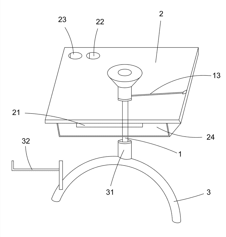
Detailed Implementation As shown in Figures 1 and 2, the utility model includes a tabletop 2 and a table frame 3. The tabletop 2 is supported by a rigid lockable gas spring 1, powered by nitrogen and using liquid oil as a locking medium. The rigid lockable gas spring 1 has a movable end 11 for the tabletop and a fixed part 12 for the frame. It is also connected to an adjustment device 13 for positioning the movable end 11. The tabletop 2 may include additional features like a sliding keyboard tray 21, pen holders 22, and cup holders 23.
Detailed connections of the rigid lockable gas spring 1 and other components are shown in Figures 2 and 3. The movable end 11 is connected to the fixed frame 14, which includes a disk-shaped bracket 144 for tabletop contact and a guiding tube 145. The guiding tube 145 is mounted on the gas spring 1, and the movable end 11 is fixed in place using a positioning block 142 and a nut 143.
As shown in Figures 1 and 4, the table frame 3 has a positioning sleeve 31 for fixing the gas spring 1, a stand 32 for a computer case, a sliding keyboard tray 21, and storage compartments 24. The adjustment device 13 can be a button or lever, placed conveniently on the table.
The model can be scaled for different users, with larger sizes for adults and smaller sizes for children. Adjusting the tabletop 2 is easy with minimal force using the adjustment device 13 for lowering, and lifting the tabletop by hand for raising. The elastic principle of the gas spring allows for smooth height adjustments, making single-person operation straightforward and eliminating the need for pins.
The movable end 11 is not limited to connecting the tabletop 2. It can also refer to other components, such as extending rods 111 fixed to the positioning sleeve 31 on the table frame 3, within the protection scope of this utility model.
Claims (9) – A Table with Adjustable Height, Easy Activation, and Rigid Locking, invented by LeiYan Gas Spring, a pioneer Chinese Gas Spring Manufacturer
- A Table with Adjustable Height, Easy Activation, and Rigid Locking, including a tabletop (2) and a table frame (3). It is characterized by: the tabletop (2) is supported on the table frame (3) by a rigid lockable gas spring (1). The rigid lockable gas spring (1) has a movable end (11) for supporting the tabletop (2) and a fixed part (12) for supporting on the table frame (3). The rigid lockable gas spring (1) is also connected to an adjustment device (13) for positioning and lifting the movable end (11) vertically.
- According to claim 1, characterized by: the tabletop (2) is provided with a fixed frame (14) connected to the movable end (11).
- According to claim 2, characterized by: the fixed frame (14) includes a bracket (144) and a guiding tube (145). The bracket (144) is disk-shaped for contacting and fixing the tabletop (2).
- According to claim 3, characterized by: the guiding tube (145) is provided with a positioning block (142) for interlocking the movable end (11).
- According to claim 4, characterized by: the movable end (11) is fixed to the positioning block (142) with a nut (143).
- According to claim 1, characterized by: the table frame (3) is provided with a positioning sleeve (31) for mounting the fixed part (12).
- According to claim 1, characterized by: the table frame (3) is provided with a computer case stand (32).
- According to claim 1, characterized by: the tabletop (2) is provided with a sliding keyboard tray (21) and storage compartments (24).
- According to claim 1, characterized by: the tabletop (2) is provided with pen holders (22) and cup holders (23).