Tag: Lockable Tension Gas Spring
A Lockable Tension Gas Spring
Patent No.:CN201487116U Date:2009-06-15
Google Patent: https://patents.google.com/patent/CN201487116U/en?oq=CN201487116U
China Patent: http://epub.cnipa.gov.cn/
Abstract
The utility model provides a lockable tension gas spring with controllable rebound after stretching. It includes a cylinder, a guide sealing sleeve, a rear plug, and a piston rod. The front end of the cylinder is fixed with a guide sealing sleeve, and the rear end is fixed with a rear plug. A fixed spacer is installed inside the cylinder. Pistons and valve body pistons are respectively arranged on the front and rear sides of the fixed spacer, and the pistons and valve body pistons are connected by a piston rod. The advantage of this structure is that a fixed spacer is added inside the cylinder, with nitrogen and liquid oil filled in the front and rear chambers, respectively. After stretching, the liquid oil enters between the valve body piston and the rear plug. Since the liquid oil is incompressible, it achieves the effect of controlling the rebound of the piston rod after the external force is removed, thus realizing the locking of the tension gas spring.
Description
A Lockable Tension Gas Spring
Technical Field The utility model relates to a gas spring, specifically a lockable tension gas spring.
Background Technology Gas springs are widely used in medical equipment, automobiles, furniture, textile equipment, and processing industries. However, there are few types of tension gas springs. Once the external force on the tension gas spring is removed, the gas spring resets, making it impossible to lock it, which limits its range of use.
Utility Model Content The technical problem this utility model aims to solve is to provide a lockable tension gas spring with controllable rebound after stretching.
To solve the above technical problems, the utility model provides a technical solution: a lockable tension gas spring, including a cylinder, a guide sealing sleeve, a rear plug, and a piston rod. The front end of the cylinder is fixed with a guide sealing sleeve, and the rear end is fixed with a rear plug. The innovation is that a fixed spacer is installed inside the cylinder, with pistons and valve body pistons respectively arranged on the front and rear sides of the fixed spacer, and the pistons and valve body pistons are connected by a piston rod.
Further, the front chamber of the fixed spacer is filled with nitrogen, and the rear chamber is filled with liquid oil.
Further, an activation rod is installed inside the piston rod, and the activation rod is fixedly connected to the valve needle of the valve body piston.
Further, a return spring is connected between the piston rod and the activation rod.
The advantages of the utility model are that a fixed spacer is added inside the cylinder, with nitrogen and liquid oil filled in the front and rear chambers, respectively. After stretching, the liquid oil enters between the valve body piston and the rear plug. Since the liquid oil is incompressible, it achieves the effect of controlling the rebound of the piston rod after the external force is removed, thus realizing the locking of the tension gas spring.
Description of Drawings
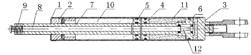
The figure is a schematic diagram of the structure of the lockable tension gas spring of the utility model.
Detailed Implementation As shown in the figure, it includes a cylinder 1, guide sealing sleeve 2, rear plug 3, fixed spacer 4, piston 5, valve body piston 6, piston rod 7, activation rod 8, and return spring 9.
The front end of the cylinder 1 is fixed with a guide sealing sleeve 2, and the rear end is connected with a rear plug 3. A fixed spacer 4 is fixedly connected inside the chamber, dividing the inner chamber of the cylinder 1 into front and rear chambers. The front chamber is filled with nitrogen 10, and the rear chamber is filled with liquid oil 11. The piston 5 and valve body piston 6 are respectively arranged in the front and rear chambers on both sides of the fixed spacer 4, and the piston 5 and valve body piston 6 are both connected to the piston rod 7, achieving linkage between the two. An activation rod 8 is connected inside the piston rod 7, and the activation rod 8 is integrated with the valve needle 12 of the valve body piston 6.
Since the rear chamber of the lockable tension spring only contains liquid oil 11 without other power sources such as nitrogen, a return spring 9 is installed. The return spring 9 is fixedly connected through the top hat of the activation rod 8 and the groove at the top end of the piston rod 7.
By activating the activation rod 8, the valve needle 12 opens, and stretching the piston rod 7 causes the piston 5 and valve body piston 6 to move upward simultaneously. The nitrogen 10 in the front chamber is compressed by the piston 5, and part of the liquid oil 11 in the rear chamber is squeezed between the valve body piston 6 and the rear plug 3. At this point, the activation rod 8 is closed. Since the liquid oil 11 between the valve body piston 6 and the rear plug 3 is incompressible, it achieves the effect of controlling the rebound of the piston rod 7, thus realizing the locking of the tension gas spring. The volume of liquid oil 11 flowing between both sides of the valve body piston 6 remains unchanged. The two sides can be considered as chambers of a container with varying cross-sectional areas, resulting in a proportional difference between the true stroke and the controllable rebound stroke. This difference can be reduced by increasing the diameter of the cylinder 1, thus achieving partial controllability.
Claims (4) A Lockable Tension Gas Spring Patent invented by LeiYan Gas Springs
1.A lockable tension gas spring, including a cylinder, a guide sealing sleeve, a rear plug, and a piston rod. The front end of the cylinder is fixed with a guide sealing sleeve, and the rear end is fixed with a rear plug. It is characterized by: a fixed spacer is installed inside the cylinder, with pistons and valve body pistons respectively arranged on the front and rear sides of the fixed spacer, and the pistons and valve body pistons are connected by a piston rod.
2.According to claim 1, the front chamber of the fixed spacer is filled with nitrogen, and the rear chamber is filled with liquid oil.
3.According to claim 1, an activation rod is installed inside the piston rod, and the activation rod is fixedly connected to the valve needle of the valve body piston.
4.According to claim 3, a return spring is connected between the piston rod and the activation rod.