Tag: locking gas spring patent
A Lockable Valve Body Piston Device with Altered Performance
Patent No.:CN113007258A Date:2021-04-27
Google Patent: https://patents.google.com/patent/CN113007258A/en?oq=CN113007258A
China Patent: http://epub.cnipa.gov.cn/
A Lockable Valve Body Piston Device with Altered Performance
Abstract
The present invention provides a lockable valve body piston device with altered performance. The device comprises a closed cavity, a piston assembly and a valve core assembly. The piston assembly includes a piston rod, a piston body and a seal. The piston body consists of a connecting part and a shaft shoulder part that are integrally connected. The shaft shoulder part is provided with a plurality of flow-through holes, extension damping holes and a plurality of compression flow-through holes. By means of the seal that is displaced by friction, the compression flow-through holes can be closed or opened to achieve the function of switching the flow rate of gas or medium oil. At the same time, the requirements of extension and compression movements are met, resulting in beneficial effects such as stable spring speed, stable working state, high safety and long service life. This solves the problem in the prior art that when adjusting the damping hole diameter, the design requirements of both extension and compression movements cannot be satisfied simultaneously, causing inconvenience in use, unstable working state, poor safety performance, and greatly reducing the consistency, smoothness and service life of the product.
Description
A Lockable Valve Body Piston Device with Altered Performance
Technical Field
The present invention relates to the field of gas springs, and specifically to a lockable valve body piston device with altered performance.
Background Art
A gas spring is a component capable of achieving functions such as support, buffering, braking, height and angle adjustment. In construction machinery, it is mainly applied to parts such as covers and doors. A gas spring mainly consists of a piston rod, a piston, a sealing guide sleeve, filling materials, a pressure cylinder, connectors, etc. The pressure cylinder is a closed cavity, filled with inert gas or an oil-gas mixture inside, and the pressure in the cavity is several times or dozens of times that of the atmospheric pressure.
When the valve body piston of a traditional gas spring undergoes extension or compression movement, the power gas or medium oil in the gas spring cylinder flows through the same damping hole. Its motion characteristics have at least the following problems:
- When the damping hole diameter is small, the damping force is relatively large, which meets the spring speed requirement of the piston’s extension movement speed. However, the compression movement will be relatively difficult, making the implementation of the compression movement difficult and inconvenient to use.
- When the damping hole diameter is large, the damping force is relatively small, which makes the compression movement easier. But the spring speed of the extension movement cannot be well damped and controlled, resulting in an unstable working state, poor safety performance, and greatly reducing the consistency, smoothness, and service life of the product.
Summary of the Invention
In view of this, the present invention provides a lockable valve body piston device with altered performance, which can solve at least one of the above problems. By means of a seal that is displaced by friction, the compression flow – through holes can be closed or opened to switch the flow rate of gas or medium oil. The piston assembly has good damping force during both extension and compression movements, achieving a good buffering effect, smooth movement, and at the same time improving safety and service life. The structure is simple, easy to manufacture, and has broad application prospects.
To achieve the above – mentioned objectives, the present invention provides the following technical solutions: A lockable valve body piston device with altered performance includes a closed cavity, a piston assembly and a valve core assembly arranged in the closed cavity. The piston assembly includes a piston rod, a piston body arranged on the piston rod, and a seal arranged on the piston body. The piston body includes a connecting part connected to the piston rod and a shaft shoulder part. The shaft shoulder part is provided with a plurality of flow – through holes, extension damping holes, and compression flow – through holes. The seal is displaced by friction to close or open the compression flow – through holes.
In some preferred embodiments, the flow – through holes are straight through – holes.
In some preferred embodiments, the flow – through holes are inclined through – holes.
In some preferred embodiments, a plurality of the flow – through holes are evenly distributed on the end face of the shaft shoulder part. A groove for placing the seal is provided on the side surface of the shaft shoulder part, and the groove is in communication with the flow – through holes, the extension damping holes, and the compression flow – through holes.
In some preferred embodiments, the groove includes a first groove and a second groove. The seal includes a first seal and a second seal. The first seal is placed in the first groove, and the second seal is placed in the second groove.
In some preferred embodiments, the depth of the groove opening on the side of the first groove close to the compression flow – through holes is consistent, and the depth of the groove opening at the end close to the extension damping holes gradually increases.
In some preferred embodiments, a valve core hole for installing the valve core assembly is provided on the shaft shoulder part.
In some preferred embodiments, a snap – fit structure adapted to the structure of the connecting end of the piston rod is provided on the connecting part.
In some preferred embodiments, the number of the extension damping holes is one.
In some preferred embodiments, the number of the flow – through holes is greater than or equal to the number of the compression flow – through holes.
Characteristics and Advantages of the Present Invention
- When the present invention undergoes compression movement, all the compression flow – through holes are opened by the friction – displaceable seal. The power – source gas or medium oil flows out through a plurality of compression flow – through holes, damping holes, and multiple flow – through holes. The transmission flow rate is greatly increased, making the compression movement easier, convenient to use, and highly efficient.
- When the present invention undergoes extension movement, the friction – displaceable seal blocks all the compression flow – through holes. At this time, the release of the power – source gas or medium oil can only flow through a plurality of flow – through holes and then through a single extension damping hole. By changing the size of the extension damping hole, it is only necessary to fully meet the spring speed requirement of the extension movement without considering the implementation of the compression movement. Thus, beneficial effects such as stable spring speed, stable working state, high safety, and long service life are achieved, solving the problem that has plagued lockable gas springs at home and abroad for many years.
- By changing the number of compression flow – through holes and through – holes to meet the maximum flow rate of gas or medium oil when the valve core is in the open state, the structure is simple, easy to manufacture, and has broad application prospects.
- The co – existence design of the inclined groove bottom of the groove at one end close to the extension damping hole and the flat groove bottom of the groove at one end close to the compression flow – through holes is beneficial to the closing or opening of the compression air flow holes, which is convenient to use and ingeniously designed.
- By designing a plurality of flow – through holes as straight through – holes or inclined through – holes, the actual volume and size requirements of the present invention are met, which is convenient to use and has broad application prospects.
Description of the Drawings
The following drawings are provided to further understand the present application, and they form a part of the present application. They are only intended to schematically explain and illustrate the present invention, rather than to limit the scope of the present invention. In the drawings:
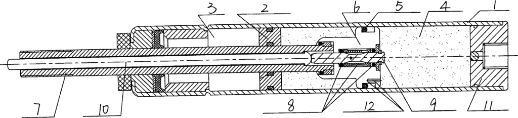
Figure 1 is a gas flow diagram of the lockable valve body piston device in extension movement in Embodiment 1 of the present application;
Figure 2 is a gas flow diagram of the lockable valve body piston device in compression movement in Embodiment 1 of the present application;
Figure 3 is a structural schematic diagram of the piston assembly with straight through – holes in Embodiment 1 of the present application;
Figure 4 is a structural schematic diagram of the piston assembly with inclined through – holes in Embodiment 2 of the present application.
Reference signs in the drawings:
- Closed cavity; 2. Valve core assembly; 3. Piston rod; 41. Connecting part; 42. Shaft shoulder part; 43. Extension damping hole; 44. Compression flow – through hole; 51. First seal; 52. Second seal; 421. Straight through – hole; 422. Inclined through – hole; 451. First groove; 452. Second groove; 4511. Inclined groove bottom.
Detailed Implementation
The following will disclose multiple embodiments of the present application through drawings, and clearly and completely describe the technical solutions of the present invention. The attached drawings that form a part of the present application are used to provide a further understanding of the present invention. The schematic embodiments and descriptions of the present invention are used to explain the present invention and do not improperly limit the present invention. Based on the embodiments of the present invention, all other embodiments obtained by those of ordinary skill in the art without creative efforts belong to the protection scope of the present invention.
It should be noted that, unless the direction is defined separately, the up, down, left, right, inner, outer and other directions involved in this text are based on the up, down, left, right, inner, outer and other directions shown in Figure 1 of the embodiment of the present application. If the specific posture changes, the directional indication will also change accordingly. The meaning of “multiple” and “a plurality of” is two or more, which is explained here together. The use of “first”, “second”, “third” and similar words does not represent any order, quantity or importance, but is only used to distinguish different components. In addition, in each embodiment of the present disclosure, the same or similar reference signs represent the same or similar components.
In the present invention, unless otherwise clearly defined and limited, terms such as “connection” and “fixation” should be understood in a broad sense. For example, “fixation” can be a fixed connection, a detachable connection, or an integral connection, unless otherwise clearly defined. For those of ordinary skill in the art, the specific meanings of the above – mentioned terms in the present invention can be understood according to specific situations.
In addition, the technical solutions between the various embodiments of the present invention can be combined with each other. However, this must be based on what can be achieved by those of ordinary skill in the art. When the combination of technical solutions is contradictory or cannot be implemented, it should be considered that such a combination of technical solutions does not exist and is not within the scope of protection required by the present invention.
Embodiment 1
Please refer to Figures 1 to 3. A lockable valve body piston device with altered performance in this embodiment includes a closed cavity 1, a piston assembly and a valve core assembly 2 arranged in the closed cavity 1. The piston assembly includes a piston rod 3, a piston body arranged on the piston rod 3, and a seal arranged on the piston body. In this embodiment, the seal is preferably a floating O – ring, but it is not limited to an O – ring, and other special – shaped seals can be selected according to the actual situation. Furthermore, the piston body includes a connecting part 41 connected to the piston rod 3 and a shaft shoulder part 42. A number of straight through – holes 421, an extension damping hole 43, and compression flow – through holes 44 are provided on the shaft shoulder part 42.
It should be noted that the number of the straight through – holes 421 can be 4, 6, or more appropriate numbers according to the actual situation.
Using the technical solution of this embodiment, as shown in Figure 1, the lockable valve body piston device of this embodiment is in the open state with the valve core opened. When the gas spring moves to the right during compression movement, the O – ring located in the groove of the piston body moves to the left by friction displacement and abuts against the left – hand side wall of the shaft shoulder part. And a number of straight through – holes 421 are arranged in the direction of the inner ring of the seal ring to keep the straight through – holes unblocked. At this time, the O – ring is separated from the groove bottom of the piston body, opening all the compression flow – through holes 44. The power – source gas or medium oil flows out through a number of compression flow – through holes 44, the damping hole 43, and a number of straight through – holes 421, forming an unobstructed and non – damped transmission channel. The transmission flow rate is greatly increased, making the compression movement easier, convenient to use, and highly efficient.
As shown in Figure 2, the lockable valve body piston device of this embodiment is in the open state with the valve core opened. When the gas spring moves to the left during extension movement, the O – ring that can be displaced by friction moves to the right and abuts against the right – hand side wall of the shaft shoulder part. At this time, the O – ring blocks all the compression flow – through holes 44, and the release of the power – source gas or medium oil can only flow through a number of straight through – holes 421 and then through a single extension damping hole 43. It should be noted that the size of the extension damping hole 43 can be set according to the spring speed requirement of the extension movement without considering the implementation of the compression movement. Therefore, this lockable valve body piston device meets the requirements of both extension and compression movements, achieving beneficial effects such as stable spring speed, stable working state, high safety, and long service life. It solves the problem in the prior art that when adjusting the damping hole diameter, the design requirements of both extension and compression movements cannot be met simultaneously, resulting in difficulties in implementing the compression movement, inconvenience in use, unstable working state, poor safety performance, and greatly reducing the consistency, smoothness, and service life of the product.
As a specific implementation method, in this embodiment, a number of straight through – holes 421 are evenly distributed on the end face of the shaft shoulder part 42 close to the connecting part 41. A first groove 451 and a second groove 452 are provided on the side surface of the shaft shoulder part 42. The seal includes a first seal 51 and a second seal 52. At the same time, the first seal 51 is placed in the first groove 451, and the second seal 52 is placed in the second groove 452. This design scheme adopts a thickened double – groove piston design, which is an innovative upgrade of the original piston in response to actual problems. The same valve core assembly can be used without changing the original valve body length, saving the development of new molds and thus reducing production costs.
As shown in Figure 3, as a specific implementation, in this embodiment, the depth of the groove opening of the first groove 451 at the end close to the compression flow – through hole 44 is consistent, and the depth of the groove opening at the end close to the extension damping hole 43 gradually increases.
Specifically, one end of the bottom of the first groove 451 is an inclined groove bottom 4511, and the other end is a flat groove bottom. The design of the co – existence of the inclined groove bottom and the flat groove bottom is beneficial to the closing or opening of the compression air flow holes. The design of the inclined groove bottom 4511 is beneficial for the separation of the groove bottom and the seal during the compression movement, ensuring the implementation of the flow – through state. It is convenient to use and ingeniously designed.
As a specific implementation, in this embodiment, a valve core hole for installing the valve core assembly 2 is provided on the shaft shoulder part 42.
As a specific implementation, in this embodiment, a snap – fit structure adapted to the structure of the connecting end of the piston rod 3 is provided on the connecting part 41. The snap – fit structure is a snap – head protrusion 411 provided at one end of the connecting part 41 away from the shaft shoulder part 42. The snap – head protrusion 411 is snapped into the annular groove of the piston rod. The structure is simple and the connection is firm.
As a specific implementation, in this embodiment, the number of the extension damping holes 43 is one, which can better ensure the stable spring speed of the extension movement, a stable working state, facilitate the design of the size of the damping hole, and improve safety and service life.
As a specific implementation, in this embodiment, the number of the straight through – holes 421 is greater than or equal to the number of the compression flow – through holes 44, which can better ensure the implementation of the compression movement.
Combined with the gas flow diagrams of the compression movement and the extension movement in Figure 1 and Figure 2, the working principle of the lockable valve body piston device of this embodiment applied to the gas spring is described as follows:
- Compression movement: Open the valve core. When the gas spring moves to the right during compression movement, the O – ring located in the groove of the piston body moves to the left by friction displacement and abuts against the left – hand side wall of the shaft shoulder part. And a number of straight through – holes 421 are arranged in the direction of the inner ring of the seal ring to keep the straight through – holes unblocked. At this time, the O – ring is separated from the groove bottom of the piston body, opening all the compression flow – through holes 44. The power – source gas or medium oil flows out through a number of compression flow – through holes 44, the damping hole 43, and a number of straight through – holes 421, forming an unobstructed and non – damped transmission channel. The transmission flow rate is greatly increased, making the compression movement easier, convenient to use, and highly efficient.
- Extension movement: Open the valve core. When the gas spring moves to the left during extension movement, the O – ring that can be displaced by friction moves to the right and abuts against the right – hand side wall of the shaft shoulder part. At this time, the O – ring blocks all the compression flow – through holes 44, and the release of the power – source gas or medium oil can only flow through a number of straight through – holes 421 and then through a single extension damping hole 43. It should be noted that the size of the extension damping hole 43 can be set according to the spring speed requirement of the extension movement without considering the implementation of the compression movement. Therefore, this lockable valve body piston device meets the requirements of both extension and compression movements, achieving beneficial effects such as stable spring speed, stable working state, high safety, and long service life. It solves the problem in the prior art that when adjusting the damping hole diameter, the design requirements of both extension and compression movements cannot be met simultaneously, resulting in difficulties in implementing the compression movement, inconvenience in use, unstable working state, poor safety performance, and greatly reducing the consistency, smoothness, and service life of the product.
Embodiment 2
The difference between this embodiment and Embodiment 1 is that, as shown in Figure 4, the flow – through holes in this embodiment are inclined through – holes 422, which are mainly applied to products of devices such as dampers and gas springs with small cylinder diameters and double cylinders.
Specifically, this lockable valve body piston device is to be applied in cylinder barrels with different pipe diameters. Therefore, it is necessary to reasonably select the maximum outer diameter of the piston assembly and the position of the flow – through holes. When the relative height of the shaft shoulder part with respect to the connecting part is limited, the design of making the flow – through holes into inclined through – holes is ingenious and reasonable.
In conclusion, through the seal displaced by friction, the compression flow – through holes are closed or opened to achieve the function of switching the flow rate of gas or medium oil. At the same time, the requirements of both extension and compression movements are met, thus achieving beneficial effects such as stable spring speed, stable working state, high safety, and long service life. This solves the problem in the prior art that when adjusting the damping hole diameter, the design requirements of both extension and compression movements cannot be met simultaneously, resulting in difficulties in implementing the compression movement, inconvenience in use, unstable working state, poor safety performance, and greatly reducing the consistency, smoothness, and service life of the product.
The above description shows and describes the preferred embodiments of the present application. However, as mentioned before, it should be understood that the present application is not limited to the forms disclosed herein. It should not be regarded as excluding other embodiments, but can be used in various other combinations, modifications, and environments, and can be modified within the scope of the concept of the present application through the above – mentioned teachings or the technologies or knowledge in related fields. Any changes and modifications made by those skilled in the art without departing from the spirit and scope of the present application shall fall within the protection scope of the appended claims of the present application.
Claims – A Lockable Valve Body Piston Device with Altered Performance, invented by LeiYan Gas Spring, a pioneer Chinese Gas Spring Manufacturer.
- A lockable valve – body piston device with altered performance, comprising a closed cavity, a piston assembly and a valve – core assembly arranged in the closed cavity, characterized in that:
The piston assembly comprises a piston rod, a piston body arranged on the piston rod, and a seal arranged on the piston body;
The piston body comprises an integrated connecting part and a shaft – shoulder part. A plurality of flow – through holes, an extension damping hole and a plurality of compression flow – through holes are arranged on the shaft – shoulder part; the seal is displaced by friction to close or open the compression flow – through holes. - The lockable valve – body piston device with altered performance according to claim 1, characterized in that the flow – through holes are straight through – holes.
- The lockable valve – body piston device with altered performance according to claim 1, characterized in that the flow – through holes are inclined through – holes.
- The lockable valve – body piston device with altered performance according to any one of claims 1 to 3, characterized in that a plurality of the flow – through holes are evenly distributed on the end face of the shaft – shoulder part, and a groove for placing the seal is arranged on the side surface of the shaft – shoulder part, and the groove is in communication with the flow – through holes, the extension damping hole and the compression flow – through holes.
- The lockable valve – body piston device with altered performance according to claim 4, characterized in that the groove comprises a first groove and a second groove, the seal comprises a first seal and a second seal, the first seal is placed in the first groove, and the second seal is placed in the second groove.
- The lockable valve – body piston device with altered performance according to claim 5, characterized in that the depth of the groove opening of the first groove at the end close to the compression flow – through holes is consistent, and the depth of the groove opening at the end close to the extension damping hole gradually increases.
- The lockable valve – body piston device with altered performance according to claim 1, characterized in that a valve – core hole for installing the valve – core assembly is arranged on the shaft – shoulder part.
- The lockable valve – body piston device with altered performance according to claim 1, characterized in that a snap – fit structure adapted to the structure of the connecting end of the piston rod is arranged on the connecting part.
- The lockable valve – body piston device with altered performance according to claim 1, characterized in that the number of the extension damping holes is one.
- The lockable valve – body piston device with altered performance according to claim 1, characterized in that the number of the flow – through holes is greater than or equal to the number of the compression flow – through holes.
A Compressible Gas Spring with an Arbitrarily Lockable Device
Patent No.:CN106090100A Date:2016-08-11
Google Patent: https://patents.google.com/patent/CN106090100A/en?oq=CN106090100A
China Patent: http://epub.cnipa.gov.cn/
A Compressible Gas Spring with an Arbitrarily Lockable Device
Abstract:
The invention relates to a compressible gas spring with an arbitrarily lockable device, which is provided with a locking device installed on the right side of the compressible gas spring. The locking device includes a fixed component that can be connected to the cylinder of the compressible gas spring and a locking component that achieves the locking of the piston rod of the compressible gas spring through the relative movement of the fixed component. The locking component is installed on the fixed component. The design of this invention is ingenious, convenient to use, sturdy, durable, and requires little external force.
Description:
A Compressible Gas Spring with an Arbitrarily Lockable Device
Technical Field: The invention relates to a compressible gas spring with an arbitrarily lockable device.
Background Technology: At present, ordinary compressible gas springs have difficulty locking in position. The compression or extension of these springs is done through an interconnected hole on the valve body piston. When a slow extension speed is required, the compression force must be increased, which becomes very heavy.
Summary of the Invention: The technical problem to be solved by this invention is to provide an arbitrarily lockable device for a compressible gas spring that is reasonably designed, compact in structure, and easy to use.
To solve the above problem, the technical solution adopted in this invention is: The basic structure of this invention includes a cylinder, a left connection piece set at the left end of the cylinder, a piston rod installed in the cylinder, a piston installed on the piston rod and located inside the cylinder, a guiding and sealing component set at the right part of the cylinder, a locking device installed on the right side of the cylinder, a right connection piece set at the right end of the piston rod, and a power source gas set inside the cylinder.
Additionally, it includes a locking device installed on the right side of the compressible gas spring. The key point is: the locking device includes a fixed component connected to the cylinder of the compressible gas spring and a locking component that achieves the locking of the piston rod of the compressible gas spring through the relative movement of the fixed component. The locking component is installed on the fixed component.
The piston rod sequentially passes through the guiding and sealing component and the locking device. The locking device includes a locking assembly sleeve on the right end of the cylinder, an end closure set at the right end of the locking assembly sleeve, a limit tube groove set between the locking assembly sleeve and the cylinder, a radial through-hole set vertically on the cylinder, a unlocking lever set vertically within the radial through-hole, a pivot point shaft set at the lower end of the outer wall of the cylinder, at least two split elastic lock blocks evenly distributed inside the cylinder, a lock block pressing sleeve set at the right side of the split elastic lock blocks, a spring set between the positioning rebate at the right end of the lock block pressing sleeve and the end closure, and an unlocking pull wire set on the outer wall of the locking assembly sleeve.
The split elastic lock blocks are configured to embrace the outer wall of the piston rod. The outer wall of the split elastic lock blocks contacts the left end rebate inner wall of the lock block pressing sleeve. An annular inner groove is set on the inner wall of the split elastic lock blocks, and a wire spring is set within the inner groove. The middle circumference of the unlocking lever surrounds the outer side of the split elastic lock blocks and is located on the left side of the lock block pressing sleeve. The upper end of the unlocking lever is connected to the pull wire head of the unlocking pull wire. The lower end of the unlocking lever passes through the radial through-hole and swings around the pivot point shaft. An oscillation gap is set between the radial through-hole and the unlocking lever along the axial direction of the locking assembly sleeve. The rightmost point of the upper end of the oscillating unlocking lever is located on the right side of the left end surface of the lock block pressing sleeve. The unlocking lever contacts the left end surface of the lock block pressing sleeve. The outer wall of the split elastic lock blocks forms an outer conical surface, and the left end rebate of the lock block pressing sleeve is equipped with an inner conical surface corresponding to the outer conical surface. The radial through-hole is a long hole set along the axial direction of the locking assembly sleeve. The length of the oscillation gap is greater than the distance between the unlocking lever and the left end surface of the lock block pressing sleeve. A sealing groove is set on the piston, and a sealing ring for sealing the piston and the inner wall of the cylinder is set within the sealing groove. The piston separates the cylinder chamber into a rod chamber and a non-rod chamber. The rod chamber is located on the right side of the non-rod chamber. A damping hole is set on the piston to communicate the sealing groove and the non-rod chamber. An air return hole is set on the piston to communicate the sealing groove and the rod chamber. A fitting gap is set between the piston and the inner wall of the cylinder. The air return hole and the damping hole respectively communicate with the bottom of the sealing groove. The guiding and sealing component includes a first sealing sleeve, a second sealing sleeve, and a third sealing sleeve sequentially set in the cylinder from left to right. Sealing rings are set between the first sealing sleeve and the second sealing sleeve, and between the second sealing sleeve and the third sealing sleeve. The first sealing sleeve, second sealing sleeve, and third sealing sleeve are respectively riveted within the right end of the cylinder chamber. A double-position sealing end plug is set at the left end of the cylinder, and the left connection piece is set at the left end of the double-position sealing end plug. The taper of the outer conical surface and the inner conical surface is either 1:5, 1:10, or 7:24.
The beneficial effects of adopting the above technical solution are as follows: The preferred design includes a return air hole and a damping hole on the piston assembly. The return air hole functions when the piston rod is compressed, while the damping hole functions when the piston rod extends. The compression force of an ordinary compressible gas spring is much greater than that of this invention. All locking components in the locking device are assembled on the locking assembly sleeve, which also serves to connect with the cylinder. The split elastic lock blocks are preferably blocks forming a complete embracing locking device with a specified internal circular diameter. The assembled embracing locking device has an outer conical surface with a specified angle. The embracing locking device is equipped with wire springs. The wire springs expand the split elastic lock blocks outward when not subjected to external force, changing the formed inner circular diameter to achieve the purpose of not embracing the piston rod. The lock block pressing sleeve and the spring are arbitrary embracing locking components. The lock block pressing sleeve acts on the split elastic lock blocks. The taper of the outer conical surface and the inner conical surface is the same. Under the action of the spring, the lock block pressing sleeve compresses the split elastic lock blocks, closing them to form an embracing locking force, locking the piston rod and stopping its extension and contraction. The unlocking of the locking device is achieved by the unlocking pull wire and unlocking lever. The unlocking lever is installed within the reserved radial through-hole of the locking assembly sleeve and is connected in a single-axis, single-end manner. It forms a mechanical lever with the pivot point shaft. The unlocking pull wire is on the other end of the unlocking lever. An external force pulls the unlocking pull wire, making the unlocking lever push the lock block pressing sleeve. The split elastic lock blocks are then expanded by the internal wire springs, opening the locking device. When the external force on the unlocking pull wire is released, the locking device locks again. The unlocking lever can also be designed as a hand-pull or handle form without using the unlocking pull wire.
This invention is ingeniously designed, easy to use, durable, and requires little external force.
Explanation of Drawings:
- Figure 1: Structural schematic diagram of the invention.
- Figure 2: Structural schematic diagram of the locking device in the invention.
- Figure 3: Structural schematic diagram of the split elastic lock block in the invention.
- Figure 4: Structural schematic diagram of the internal groove in the invention.
- Figure 5: Structural schematic diagram of the lock block pressing sleeve in the invention.
Key Components:
- Right connection piece
- Piston rod
- Locking device
- Cylinder
- Guiding and sealing component
- Piston
- Power source gas
- Double-position sealing end plug
- Left connection piece
- Damping hole
- Air return hole
- Fitting gap
- First sealing sleeve
- Second sealing sleeve
- Third sealing sleeve
- Locking assembly sleeve
- Limit tube groove
- Radial through-hole
- End closure
- Unlocking lever
- Pivot point shaft
- Split elastic lock block
- Lock block pressing sleeve
- Unlocking pull wire
- Pull wire head
- Internal groove
- Wire spring
- Outer conical surface
- Inner conical surface
- Positioning rebate
- Spring
Specific Implementation: As shown in Figures 1-5, this invention includes a cylinder (4), a left connection piece (9) set at the left end of the cylinder (4), a piston rod (2) set inside the cylinder (4), a piston (6) set on the piston rod (2) and located inside the cylinder (4), a guiding and sealing component (5) set at the right part of the cylinder (4), a locking device (3) set at the right side of the cylinder (4), a right connection piece (1) set at the right end of the piston rod (2), and a power source gas (7) set inside the cylinder (4).
The piston rod (2) sequentially passes through the guiding and sealing component (5) and the locking device (3). The locking device (3) includes a fixed component connected to the cylinder (4) of the compressible gas spring and a locking component that achieves the locking of the piston rod (2) through the relative movement of the fixed component. The locking component is installed on the fixed component.
The locking device (3) includes a locking assembly sleeve (16) on the right end of the cylinder (4), an end closure (19) set at the right end of the locking assembly sleeve (16), a limit tube groove (17) set between the locking assembly sleeve (16) and the cylinder (4), a radial through-hole (18) set vertically on the cylinder (4), a unlocking lever (20) set vertically within the radial through-hole (18), a pivot point shaft (21) set at the lower end of the outer wall of the cylinder (4), at least two split elastic lock blocks (22) evenly distributed inside the cylinder (4), a lock block pressing sleeve (23) set at the right side of the split elastic lock blocks (22), a spring (32) set between the positioning rebate (31) at the right end of the lock block pressing sleeve (23) and the end closure (19), and an unlocking pull wire (24) set on the outer wall of the locking assembly sleeve (16).
The split elastic lock blocks (22) embrace the outer wall of the piston rod (2). The outer wall of the split elastic lock blocks (22) contacts the left end rebate inner wall of the lock block pressing sleeve (23). An annular inner groove (26) is set on the inner wall of the split elastic lock blocks (22), and a wire spring (27) is set within the inner groove (26). The middle circumference of the unlocking lever (20) surrounds the outer side of the split elastic lock blocks (22) and is located on the left side of the lock block pressing sleeve (23). The upper end of the unlocking lever (20) is connected to the pull wire head (25) of the unlocking pull wire (24).
The lower end of the unlocking lever (20) passes through the radial through-hole (18) and swings around the pivot point shaft (21). An oscillation gap is set between the radial through-hole (18) and the unlocking lever (20) along the axial direction of the locking assembly sleeve (16). The rightmost point of the upper end of the oscillating unlocking lever (20) is located on the right side of the left end surface of the lock block pressing sleeve (23). The unlocking lever (20) contacts the left end surface of the lock block pressing sleeve (23). The outer wall of the split elastic lock blocks (22) forms an outer conical surface (28), and the left end rebate of the lock block pressing sleeve (23) is equipped with an inner conical surface (30) corresponding to the outer conical surface (28). The radial through-hole (18) is a long hole set along the axial direction of the locking assembly sleeve (16).
The length of the oscillation gap is greater than the distance between the unlocking lever (20) and the left end surface of the lock block pressing sleeve (23), thereby increasing the oscillation stroke to ensure complete disengagement.
A sealing groove is set on the piston (6). A sealing ring for sealing the piston (6) and the inner wall of the cylinder (4) is set within the sealing groove. The piston (6) separates the cylinder chamber into a rod chamber and a non-rod chamber. The rod chamber is located on the right side of the non-rod chamber. A damping hole (10) is set on the piston (6) to communicate the sealing groove and the non-rod chamber. An air return hole (11) is set on the piston (6) to communicate the sealing groove and the rod chamber. A fitting gap (12) is set between the piston (6) and the inner wall of the cylinder (4).
The air return hole (11) and the damping hole (10) respectively communicate with the bottom of the sealing groove.
The guiding and sealing component (5) includes a first sealing sleeve (13), a second sealing sleeve (14), and a third sealing sleeve (15) sequentially set in the cylinder (4) from left to right. Sealing rings are set between the first sealing sleeve (13) and the second sealing sleeve (14), and between the second sealing sleeve (14) and the third sealing sleeve (15). The first sealing sleeve (13), second sealing sleeve (14), and third sealing sleeve (15) are respectively riveted within the right end of the cylinder chamber.
A double-position sealing end plug (8) is set at the left end of the cylinder (4), and the left connection piece (9) is set at the left end of the double-position sealing end plug (8).
The taper of the outer conical surface (28) and the inner conical surface (30) is either 1:5, 1:10, or 7:24, achieving quick disengagement and fit.
The preferred design includes five air return holes (11) and one damping hole (10) on the piston assembly. The air return holes (11) function when the piston rod (2) is compressed, while the damping hole (10) functions when the piston rod (2) extends. The compression force of an ordinary compressible gas spring is much greater than that of this invention. All locking components in the locking device (3) are assembled on the locking assembly sleeve (16), which also serves to connect with the cylinder (4). The split elastic lock blocks (22) are preferably four blocks forming a complete embracing locking device with a specified internal circular diameter. The assembled embracing locking device has an outer conical surface (28) with a specified angle. The embracing locking device is equipped with wire springs (27). The wire springs (27) expand the split elastic lock blocks (22) outward when not subjected to external force, changing the formed inner circular diameter to achieve the purpose of not embracing the piston rod (2). The lock block pressing sleeve (23) and the spring (32) are arbitrary embracing locking components. The lock block pressing sleeve (23) acts on the split elastic lock blocks (22). The taper of the outer conical surface (28) and the inner conical surface (30) is the same. Under the action of the spring (32), the lock block pressing sleeve (23) compresses the split elastic lock blocks (22), closing them to form an embracing locking force, locking the piston rod (2) and stopping its extension and contraction. The unlocking of the locking device (3) is achieved by the unlocking pull wire (24) and unlocking lever (20). The unlocking lever (20) is installed within the reserved radial through-hole (18) of the locking assembly sleeve (16) and is connected in a single-axis, single-end manner. It forms a mechanical lever with the pivot point shaft (21). The unlocking pull wire (24) is on the other end of the unlocking lever (20). An external force pulls the unlocking pull wire (24), making the unlocking lever (20) push the lock block pressing sleeve (23). The split elastic lock blocks (22) are then expanded by the internal wire springs (27), opening the locking device. When the external force on the unlocking pull wire (24) is released, the locking device (3) locks again. The unlocking lever (20) can also be designed as a hand-pull or handle form without using the unlocking pull wire (24).
This invention is ingeniously designed, easy to use, sturdy, durable, and requires little external force.
It should be noted that the above embodiments are only used to illustrate the technical solutions of this invention and not to limit them. Although this invention has been described in detail with reference to the aforementioned embodiments, those skilled in the art should understand that they can still make modifications to the technical solutions described in the above embodiments or make equivalent replacements for some of the technical features. It is evident that those skilled in the art can combine multiple technical solutions of this invention. These modifications or replacements do not deviate from the spirit and scope of the technical solutions of the embodiments of this invention.
Claims: A Compressible Gas Spring with an Arbitrarily Lockable Device, invented by LeiYan Gas Spring, a pioneer Chinese Gas Spring Manufacture
- A compressible gas spring with an arbitrarily lockable device, characterized by the inclusion of a locking device (3) installed on the right side of the compressible gas spring. The locking device (3) includes a fixed component connected to the cylinder (4) of the compressible gas spring and a locking component that achieves the locking of the piston rod (2) of the compressible gas spring through the relative movement of the fixed component. The locking component is installed on the fixed component.
- According to claim 1, the compressible gas spring with an arbitrarily lockable device is characterized in that the locking device (3) includes a locking assembly sleeve (16) fitted on the right end of the cylinder (4), an end closure (19) set at the right end of the locking assembly sleeve (16), a limit tube groove (17) set between the locking assembly sleeve (16) and the cylinder (4), a radial through-hole (18) set vertically on the cylinder (4), a unlocking lever (20) set vertically within the radial through-hole (18), a pivot point shaft (21) set at the lower end of the outer wall of the cylinder (4), at least two split elastic lock blocks (22) evenly distributed inside the cylinder (4), a lock block pressing sleeve (23) set at the right side of the split elastic lock blocks (22), a spring (32) set between the positioning rebate (31) at the right end of the lock block pressing sleeve (23) and the end closure (19), and an unlocking pull wire (24) set on the outer wall of the locking assembly sleeve (16). The split elastic lock blocks (22) embrace the outer wall of the piston rod (2). The outer wall of the split elastic lock blocks (22) contacts the left end rebate inner wall of the lock block pressing sleeve (23). An annular inner groove (26) is set on the inner wall of the split elastic lock blocks (22), and a wire spring (27) is set within the inner groove (26). The middle circumference of the unlocking lever (20) surrounds the outer side of the split elastic lock blocks (22) and is located on the left side of the lock block pressing sleeve (23). The upper end of the unlocking lever (20) is connected to the pull wire head (25) of the unlocking pull wire (24). The lower end of the unlocking lever (20) passes through the radial through-hole (18) and swings around the pivot point shaft (21). An oscillation gap is set between the radial through-hole (18) and the unlocking lever (20) along the axial direction of the locking assembly sleeve (16). The rightmost point of the upper end of the oscillating unlocking lever (20) is located on the right side of the left end surface of the lock block pressing sleeve (23). The unlocking lever (20) contacts the left end surface of the lock block pressing sleeve (23).
- According to claim 2, the compressible gas spring with an arbitrarily lockable device is characterized in that the outer wall of the split elastic lock blocks (22) forms an outer conical surface (28), and the left end rebate of the lock block pressing sleeve (23) is equipped with an inner conical surface (30) corresponding to the outer conical surface (28).
- According to claim 3, the compressible gas spring with an arbitrarily lockable device is characterized in that the radial through-hole (18) is a long hole set along the axial direction of the locking assembly sleeve (16).
- According to claim 3, the compressible gas spring with an arbitrarily lockable device is characterized in that the length of the oscillation gap is greater than the distance between the unlocking lever (20) and the left end surface of the lock block pressing sleeve (23).
- According to claim 1, the compressible gas spring with an arbitrarily lockable device is characterized in that a left connection piece (9) is set at the left end of the cylinder (4), a guiding and sealing component (5) is set at the right part of the cylinder (4), a locking device (3) is set at the right side of the cylinder (4), a right connection piece (1) is set at the right end of the piston rod (2), and a power source gas (7) is set inside the cylinder (4). The piston rod (2) sequentially passes through the guiding and sealing component (5) and the locking device (3). A sealing groove is set on the piston (6). A sealing ring for sealing the piston (6) and the inner wall of the cylinder (4) is set within the sealing groove. The piston (6) separates the cylinder chamber into a rod chamber and a non-rod chamber. The rod chamber is located on the right side of the non-rod chamber. A damping hole (10) is set on the piston (6) to communicate the sealing groove and the non-rod chamber. An air return hole (11) is set on the piston (6) to communicate the sealing groove and the rod chamber. A fitting gap (12) is set between the piston (6) and the inner wall of the cylinder (4).
- According to claim 6, the compressible gas spring with an arbitrarily lockable device is characterized in that the air return hole (11) and the damping hole (10) respectively communicate with the bottom of the sealing groove.
- According to claim 6, the compressible gas spring with an arbitrarily lockable device is characterized in that the guiding and sealing component (5) includes a first sealing sleeve (13), a second sealing sleeve (14), and a third sealing sleeve (15) sequentially set in the cylinder (4) from left to right. Sealing rings are set between the first sealing sleeve (13) and the second sealing sleeve (14), and between the second sealing sleeve (14) and the third sealing sleeve (15). The first sealing sleeve (13), second sealing sleeve (14), and third sealing sleeve (15) are respectively riveted within the right end of the cylinder chamber.
- According to claim 6, the compressible gas spring with an arbitrarily lockable device is characterized in that a double-position sealing end plug (8) is set at the left end of the cylinder (4), and the left connection piece (9) is set at the left end of the double-position sealing end plug (8).
- According to claim 3, the compressible gas spring with an arbitrarily lockable device is characterized in that the taper of the outer conical surface (28) and the inner conical surface (30) is either 1:5, 1:10, or 7:24.
Auto-Reset Lockable Gas Spring
Patent No.:CN201198885 Date:2008-04-28
Google Patent: https://patents.google.com/patent/CN201198885Y/en?oq=CN201198885
China Patent: http://epub.cnipa.gov.cn/
Abstract
This utility model provides an auto-reset lockable gas spring, composed of a cylinder, piston, and rear plug. The floating piston inside the cylinder divides it into two chambers, filled with nitrogen and hydraulic oil respectively. In the chamber filled with hydraulic oil, the piston is sealed with an O-ring. The piston is connected to a piston rod, valve core assembly, and valve needle. A wide groove is created on the piston, with the O-ring situated in the groove, and a reset hole is also made on the piston. This design incorporates a reset hole in the piston of the gas spring, and through the coordination of the piston, reset hole, and O-ring, it not only achieves automatic resetting but also enables a slow and steady extension and resetting function due to the internal pressure of the gas spring when external force is lost. This function is applicable to any type of lockable gas spring.
Description
A Type of Auto-Reset Lockable Gas Spring
Technical Field The utility model relates to a gas spring, specifically a gas spring that can automatically reset and be lockable.
Background Technology Currently, the market offers various types of lockable gas springs, but they are limited to the locking adjustment function and cannot achieve automatic resetting. With the widespread application of gas springs, devices such as bus seats, airplane cabin seats, and other single gas, gas-oil mixed, and gas-oil separated types of equipment can all be designed for automatic resetting to enhance convenience. However, there has not been an auto-reset lockable spring that can meet these needs.
Utility Model Content This utility model provides an auto-reset lockable gas spring.
To solve the above technical problems, this utility model provides an auto-reset lockable gas spring, which consists of a cylinder, a piston, and a rear plug. Inside the cylinder is a floating piston that divides the cylinder into two chambers filled with nitrogen and liquid oil, respectively. In the chamber filled with hydraulic oil, the piston is sealed with an O-ring. The piston is connected to a piston rod, valve core assembly, and valve needle. The characteristic of this design is that the piston has a wide groove with an O-ring in it and a reset hole on the piston.
The width of the groove on the piston is twice the diameter of the O-ring.
The reset hole consists of a vertical hole and a horizontal hole.
The horizontal hole of the reset hole is located at the centerline of the groove width on the piston.
Advantages of the Structure: The innovation of this structure lies in adding a reset hole to the piston, and through the coordination of the piston, reset hole, and O-ring, it achieves automatic resetting. In the absence of external force, due to the internal pressure of the gas spring, it can achieve a slow return of gas in both chambers, slowly extending and resetting. This function is applicable to any type of lockable gas spring.
Description of Drawings
Figure 1 is a schematic diagram of the structure of this utility model.
Figure 2 is an enlarged view of the piston of this utility model.
Detailed Implementation As shown in Figures 1 and 2, the bottom of the gas spring cylinder 1 is fixed with a rear plug 11, and inside it is a floating piston 2. The floating piston 2 divides the cylinder 1 into two chambers, filled with nitrogen 3 and liquid oil 4, respectively. In the chamber filled with hydraulic oil 4, the piston 6 is sealed with an O-ring 5. The piston 6 is connected to the valve core assembly 8, valve needle 9, piston rod 7, and the activation rod 10 on the piston rod 7. The main innovation of this structure lies in increasing the width of the groove 15 on the piston 6 to twice the diameter of the O-ring 5 and adding a reset hole 12 on the piston 6. The reset hole 12 consists of a vertical hole 13 and a horizontal hole 14, with the horizontal hole 14 located at the centerline of the groove width on the piston 6. The O-ring 5 moves up and down within the wide groove 15 on the piston 6 along the horizontal hole 14 of the reset hole 12, sealing as the lockable gas spring is compressed and extended. When the lockable gas spring is in a compressed state, the O-ring 5 floats to the upper end of the horizontal hole 14 of the reset hole 12 for sealing. During the extension adjustment, the O-ring 5 floats to the lower end of the horizontal hole 14 of the reset hole 12 for sealing. The compression and extension adjustment of this spring are the same as other lockable gas springs. The difference is that in the absence of external force, due to the internal pressure of the lockable gas spring, the O-ring 5 also floats to the lower end of the horizontal hole 14 of the reset hole 12, thus achieving the function of slowly returning gas in both chambers and slowly extending and resetting. This function is suitable for any type of lockable gas spring, including single gas, gas-oil mixed, gas-oil separated (including front separation and rear separation) types.
Claims (4) – Auto-Reset Lockable Gas Spring invented by LeiYan Gas Springs
- A Type of Auto-Reset Lockable Gas Spring, consisting of a cylinder, piston, and rear plug, with a floating piston built inside the cylinder. The floating piston divides the cylinder into two chambers filled with nitrogen and liquid oil respectively. In the chamber filled with hydraulic oil, the piston is sealed with an O-ring. The piston is connected to a piston rod, valve core assembly, and valve needle. It is characterized by: a wide groove on the piston, with the O-ring situated in the groove, and a reset hole on the piston.
- According to claim 1, the width of the groove on the piston is twice the diameter of the O-ring.
- According to claim 1, the reset hole consists of a vertical hole and a horizontal hole.
- According to claim 3, the horizontal hole of the reset hole is located at the centerline of the groove width on the piston.
Controllable adjustable two-way rigidity locking gas spring
Patent No.:CN2746201 Date:2004.11.11
Google Patent: https://patents.google.com/patent/CN2746201Y/en?oq=CN2746201
China Patent: http://epub.cnipa.gov.cn/
Abstract
The utility model discloses a controllable adjustable two-way rigidity locking gas spring, overcoming the defect that the existing spring only can be one-way rigidity locked in prior art. The utility model consists of a cylindrical shell, a cylinder rod and a piston. The piston is provided with an orifice and a center through-hole and a valve needle is provided inside the center through-hole. One end of the valve needle is connected with a regulating stem. The other end of the cylindrical shell is sealed by a rear block and a floating piston is provided between the piston and the rear block. Thus, the cylindrical shell is divided into an air chamber and a hydraulic-oil chamber. A float trap is provided between the piston and the floating piston. The utility model can adopt the method of the existing product and adjust the latched position at can by the regulating stem. The function of two-way rigidity locking can be achieved after loosening hands. The effect of hydraulic damping is likewise provided and the resistance to shock is good. The utility model has the advantages of simple structure, original conception, good sealing property, etc. The utility model can be extensively used in the fields of medical bed for turning body, aviation, vehicle seat for adjusting back support, etc.
Description
Controllable two-way rigid locking air spring
Technical field
The air spring manufacturing technology field that the utility model relates to and a kind ofly is used for that medical bed is leaned to one side, aviation and vehicle seat back are regulated especially refers to the two-way rigid locking device of air spring.
Background technique
The invention of air spring technology and the history of using existing decades thereof, that sells on the market is of a great variety, and it mainly utilizes the pressurized gas in the sealed cylinder block, through going to promote the motion of piston rod after the damping of hydraulic piston.For example 93110703.2 applications for a patent for invention that are called ” hydraulically controlled pneumatic elastic jackstay ” of disclosed application number on February 16th, 1994, ” piston rod second half section cavity pneumatic or the hydraulic control elastic jackstay is slightly larger than preceding half section cavity; be provided with poppet shaft in its second half section cavity; form main damping oil pocket between the front-end face of poppet shaft ear end face and cylinder body rear portion inner carrier; piston rod between the inwall of the outer wall of one section body between big end of its afterbody and the stuffing box gland and cylinder body relevant position, form auxilliary damping oil pocket, assist the damping oil pocket and when poppet shaft is opened, be connected by the damping hole on the big end of piston rod afterbody.” this product has that strut elasticity is strong, speed is easy to control and advantage such as arbitrary position locking.But anatomize this patent application prospectus, in conjunction with practical application experience, the claimant has found that this product has the defective that can not reach two-way rigid locking, and promptly when being subjected to pressure stress, this series products can only reach elastic locking, but not rigid locking.This elastic locking scope and air chamber air pressure are inversely proportional to.Therefore, this series products be applied to medical bed lean to one side to support the time, must have rocking to a certain degree, it is required to satisfy clinical treatment.Manufacturer is in order to dwindle its elastic locking distance, has to improve air chamber air pressure offsetting external force so that product when making the requirement for gas sealing ability improve again and again, cost of production increases greatly.
The model utility content
The technical problems to be solved in the utility model is the air spring product that a kind of novelty is provided to society, this product is arbitrarily adjusted locked position by adjustable lever, can reach two-way rigid locking function after loosing one’s grip, to overcome deficiency that only possesses unidirectional rigid locking function and the defective that prior art exists, satisfied more technical fields are required for the installation of hydraulically controlled pneumatic elastic parts.
The technological scheme that its technical problem that solves the utility model adopts is: controllable two-way rigid locking air spring comprises that a cylindrical shell and an end insert into the inner the piston rod in chamber, and the piston rod end of stretching into the circular cylindrical shell intracoelomic cavity is connected with piston; Piston is established damping hole and central through bore, is provided with needle in the central through bore, and needle one end is connected with adjustable lever; The other end of cylindrical shell is established floating piston by back stifled the sealing between piston and back blocking up, the circular cylindrical shell intracoelomic cavity is divided into air chamber and fluid chamber, establishes floating valve between described piston and floating piston.
Described floating valve is embedded in the inward flange of cylindrical shell, fixes along the axle directions X; Inward flange and floating valve circumferential surface middle part are provided with seal ring.
Described floating valve includes spool, Returnning spring and Sealing.
The controllable two-way rigid locking air spring product of the utility model is set up a floating valve between piston and floating piston, this floating valve is embedded in the inward flange of cylindrical shell, fixes along the axle directions X.This product is under lock state, and when piston rod was subjected to pressure stress, piston promoted hydraulic oil and flows, and makes the floating valve quick closedown, and air spring is realized the rigid locking function.Therefore, this product air chamber air pressure needn’t fill De Taigao, only needing normally to promote piston rod bounce-back answer gets final product, its rigid locking task in compressive state is finished by floating valve entirely, can reduce in the air chamber manufacture process requirement greatly for gas sealing ability, promptly can save production cost, can prevent gas leakage again.This product can be continued to use the existing product mode and arbitrarily adjust locked position by adjustable lever in use, but can reach two-way rigid locking state after loosing one’s grip.During bounce-back, have the hydraulic damping effect equally, shock-absorbing capacity is good.This product structure is simple, novel, anti-leak gas performance is good, can be widely used in that medical bed is leaned to one side, field such as aviation and vehicle seat back adjusting.
Description of drawings
Fig. 1 is the utility model structural representation.
Fig. 2 is the utility model locking stroke adjusting device structural representation.
Embodiment
As shown in Figure 1 and Figure 2, the controllable two-way rigid locking air spring of the utility model comprises that with axle X be the cylindrical shell 23 of a core and the piston rod 24 that an end inserts into the inner the chamber, and piston rod 24 ends of stretching into cylindrical shell 23 inner chambers are connected with piston 5.The other end of cylindrical shell 23 is given airtight by back stifled 14, the center of back stifled 14 is embedded with steel ball 13 so that charge into high pressure nitrogen.Cylindrical shell 23 inner chambers adjacent with back stifled 14 are air chamber 12, establish floating piston 15 between piston 5 and back block up 14, and cylindrical shell 23 inner chambers are divided into air chamber 12 and fluid chamber 8.Floating piston 15 circumferential surfaces are embedded with seal ring, realize and the partition of cylindrical shell 23 inwalls that piston 5 is isolated into fluid chamber 8 B chamber and C chamber again.Stretch out at piston rod 24 roots of cylindrical shell 23 outsides and establish cushion collar 1, to slow down external impact.For the smooth running that guarantees piston rod 24 and prevent the hydraulic oil seepage, cylindrical shell 23 inner chambers that are away from stifled 14 1 ends in back are established guide sleeve 2, seal ring 3 and spacer 22 successively.As shown in Figure 2, be provided with the locked position controlling device between B chamber and the C chamber, described locked position controlling device comprises the needle 19 of being located at piston 5 central through bores, is located at the damping hole 26 on piston 5 peripheral wall and is positioned at piston rod 24 center holes and peak at the adjustable lever 25 of needle 19.For guaranteeing the sealability of piston B chamber, 5 both sides and C chamber, needle 19 is with seal ring 20, septulum cover 6, seal ring 20 and jump ring 7 from left to right successively.For prevent hydraulic oil from the C chamber through piston rod 24 center hole seepages, establish pad 21 and seal ring 4 at the piston rod 24 and the joint of piston 5.With respect to existing product, the utility model product is set up floating valve 9 between piston 5 and floating piston 15, this floating valve 9 is embedded in the inward flange 10 of cylindrical shell 23, fix along the axle directions X, inward flange 10 is established a seal ring 11 with floating valve 9 circumferential surfaces middle part, prevents that hydraulic oil is from seepage between floating valve 9 circumferential surfaces and cylindrical shell 23 internal chamber walls.Floating valve 9 is provided with spool 18, Returnning spring 17 and is used for the Sealing 16 of plane sealing.
Continue to narrate in conjunction with the accompanying drawings working principle of the present utility model below.Before this product export, earlier inject hydraulic oil toward fluid chamber 8, stifled 14 charge into air chamber 12 with nitrogen from the back, with steel ball 13 shutoff sealing.
In conjunction with Fig. 1, shown in Figure 2, when the locked position of the utility model product is regulated, force in adjustable lever 25 and back down needle 19, the hydraulic circuit between B chamber and the C chamber thin bar 28 and septulum overlap 6 inwalls through needle 19 middle parts gap, septulum overlap 6 cinclides 27, piston 5 damping holes 26 and mutual conduction.Then, drive pistons 5 and move to right by promoting piston rod 24, behind the hydraulic oil pressurized of B chamber, oil pressure is acted on spool 18 and make it to move to right, 9 moments of floating valve close, and B chamber hydraulic oil can’t flow to the A chamber.Meanwhile, because B chamber hydraulic oil pressurized, beginning flow to the C chamber after gap, septulum that thin bar 28 in needle 19 middle parts and septulum overlap 6 inwalls overlap 6 cinclides 27, piston 5 damping holes 26.After reaching the required locked position of user, unclamp adjustable lever 25, the external pressure that B chamber hydraulic oil bears disappears, air chamber 12 promotes floating piston 15 and moves to left, and spool 18 is opened under spring 17 effects again, oil pressure is passed to the B chamber by the A chamber, and oil pressure pushes back to piston 5 central through bores with needle 19, and oil circuit cuts off and closes between B chamber and the C chamber.At this moment, when piston rod 24 was subjected to outside tensile stress, because C chamber hydraulic oil is in the state of sealing, piston rod 24 was in the rigid locking state.And when piston rod 24 was subjected to outside pressure stress, B chamber hydraulic oil pressurized, oil pressure acted on spool 18, spool 18 is moved to right, and 9 moments of floating valve close, and B chamber hydraulic oil can’t flow to the A chamber, B chamber hydraulic oil is in the state of sealing, and piston rod 24 is in the rigid locking state.
When the locked position of the utility model product is automatically reset, only force in adjustable lever 25 and back down needle 19, and piston rod 24 is not applied external force.As in the previous paragraph, hydraulic circuit between B chamber and the C chamber thin bar 28 and septulum overlap 6 inwalls through needle 19 middle parts gap, septulum overlap 6 cinclides 27, piston 5 damping holes 26 and mutual conduction, air chamber 12 promotes floating piston 15 and moves to left, hydraulic oil flows into the B chamber through floating valve 9 by the A chamber, B chamber oil pressure acts on piston 5 right flanks, and piston 5 and piston rod 24 are released cylindrical shell 23 inner chambers.The volume that air chamber 12 increases equals the volume that piston rod 24 stretches out the C chamber.Simultaneously the C chamber volume that causes reduces because piston 5 and piston rod 24 move to left, and C chamber hydraulic oil overlaps the gap that 6 cinclides 27, the thin bar 28 in needle 19 middle parts and septulum overlap 6 inwalls through piston 5 damping holes 26, septulum, is back to the B chamber.C chamber hydraulic oil produces liquid damping buffering effect to piston 5 left surfaces in flowing to B chamber process, thus realize piston rod 24 slowly and elasticity is stretched out, its speed of stretching out then depends on the diameter dimension of piston 5 damping holes 26.
Claims (3)
1, a kind of controllable two-way rigid locking air spring comprises that a cylindrical shell and an end insert into the inner the piston rod in chamber, and the piston rod end of stretching into the circular cylindrical shell intracoelomic cavity is connected with piston; Piston is established damping hole and central through bore, is provided with needle in the central through bore, and needle one end is connected with adjustable lever; The other end of cylindrical shell is established floating piston by back stifled the sealing between piston and back blocking up, the circular cylindrical shell intracoelomic cavity is divided into air chamber and fluid chamber, it is characterized in that establishing floating valve between described piston and the floating piston.
2, controllable two-way rigid locking air spring as claimed in claim 1 is characterized in that described floating valve is embedded in the inward flange of cylindrical shell, fixes along the axle directions X; Inward flange and floating valve circumferential surface middle part are provided with seal ring.
3, controllable two-way rigid locking air spring as claimed in claim 1 or 2 is characterized in that described floating valve includes spool, Returnning spring and Sealing.