Tag: Rotating and Height-Adjustable Auto-Reset Seat Lifter gas spring
Rotating and Height-Adjustable Auto-Reset Seat Lifter gas spring
Patent No.:CN101564245 Date:2009-06-15
Google Patent: https://patents.google.com/patent/CN101564245A/en?oq=CN101564245
China Patent: http://epub.cnipa.gov.cn/
A Rotating and Height-Adjustable Auto-Reset Seat Lifter gas spring
Abstract
This invention relates to a seat lifter gas spring that can achieve automatic resetting in both height adjustment and rotation. It includes an outer tube, an inner tube, a guide sealing sleeve, a valve body, and a piston. The front end of the outer tube is connected to a guide sealing sleeve, and the end is fixed with a valve body. The inner chamber connects with the inner tube, which contains a piston. The top of the piston is connected to a rotating reset block, and another identical rotating reset block is fixed at the top of the inner tube. The circumferential surface of the piston has an annular groove, which houses an O-ring. The center of the bottom line has a return air hole connecting the front and rear chambers of the piston. By setting angled cylindrical positioning blocks on the inner tube and piston, the lifter achieves rotational reset. The O-ring on the piston allows the return air hole to enable height reset, resulting in a simple structure, low manufacturing cost, strong versatility, and easy promotion.
Description
A Rotating and Height-Adjustable Auto-Reset Seat Lifter gas spring
Technical Field This invention relates to a lifter, specifically a rotating and height-adjustable auto-reset seat lifter.
Background Technology Gas springs have been widely used in medical equipment, automobiles, furniture, textile equipment, and processing industries. However, traditional gas spring seat lifters cannot achieve resetting for height adjustment or rotation, limiting their range of use.
Summary of the Invention The technical problem this invention aims to solve is to provide a seat lifter that can achieve automatic resetting for both height adjustment and rotation.
To solve the above technical problems, the invention’s technical solution is: a rotating and height-adjustable auto-reset seat lifter, comprising an outer tube, an inner tube, a guide sealing sleeve, a valve body, and a piston. The front end of the outer tube is connected to a guide sealing sleeve, and the end is fixed with a valve body. The inner chamber connects with the inner tube, which contains a piston. The top of the piston is connected to a rotating reset block, and another identical rotating reset block is fixed at the top of the inner tube. The circumferential surface of the piston has an annular groove, which houses an O-ring. The center of the bottom line has a return air hole connecting the front and rear chambers of the piston.
Further, the rotating reset block is a cylindrical block with a sloped end face, with an angle of 40-50°.
Further, the width of the annular groove is twice the diameter of the O-ring.
Advantages of the Invention By setting angled cylindrical positioning blocks on the inner tube and piston, the lifter achieves rotational reset. The O-ring on the piston allows the return air hole to enable height reset, resulting in a simple structure, low manufacturing cost, strong versatility, and easy promotion.
Description of Drawings
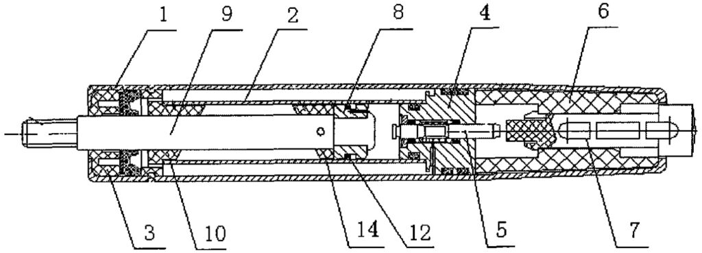
Figure 1 is a schematic diagram of the structure of the auto-reset seat lifter.
Figure 2 is a partial schematic diagram of the auto-reset seat lifter.
Detailed Implementation As shown in Figures 1 and 2, it includes an outer tube 1, an inner tube 2, a guide sealing sleeve 3, a valve body 4, a valve needle 5, a valve seat 6, an activation rod 7, a piston 8, a piston rod 9, a rotating reset block 10, another rotating reset block 14, an annular groove 11, and an O-ring 12.
The front end of the outer tube 1 is connected to a guide sealing sleeve 3, and the end is fixed with a valve body 4. The valve body 4 inner chamber connects with a valve needle 5, with the bottom end fixed to the valve seat 6. The valve seat 6 contains an activation rod 7, which connects with the valve needle 5 inside the valve body 4. The inner chamber of the outer tube 1 connects with an inner tube 2, which contains a piston 8. The piston 8 connects with a piston rod 9 that passes through the guide sealing sleeve 3.
To achieve horizontal rotational reset of the lifter, the top ends of the piston 8 and the inner tube 2 are connected to identical cylindrical rotating reset blocks 10 and 14 with sloped end faces. The angles of these sloped end faces are 40-50°. As shown in Figure 2, the specific working principle is: when the seat lifter activates the valve needle 5 for automatic reset, the piston 8 and its top rotating reset block 10 move upward under internal pressure. The sharp point A of the rotating reset block 10 cannot stop relative to the sharp point B of the rotating reset block 14 until point A, B’ of block 10 aligns with point A’, B of block 14, completing the rotational reset of the seat lifter.
To achieve vertical height reset of the piston rod 9, the circumferential surface of the piston 8 has an annular groove 11 with an O-ring 12. The center of the groove bottom has a return air hole 13 connecting the front and rear chambers of the piston 8. The width of the annular groove 11 is twice the diameter of the O-ring 12, and its depth is slightly less than the diameter of the O-ring 12. The working principle is: when the valve needle 5 is closed and the external force on the seat lifter is greater than or equal to the support force generated by the internal pressure of the piston 8, the O-ring 12, due to friction, rests at the C end of the annular groove 11. When the seat lifter activates the valve needle 5 for automatic reset, the O-ring 12 is forced to rest at the D end of the annular groove 11. At this time, the gas at the front end of the piston 8 enters the rear end of the piston 8 through the return air hole 13, generating an upward thrust on the piston rod 9 and piston 8, achieving the height reset of the seat.
Claims (3) Rotating and Height-Adjustable Auto-Reset Seat Lifter gas spring, invented by LeiYan Gas Spring, a pioneer Chinese Gas Spring Manufacturer
- A rotating and height-adjustable auto-reset seat lifter, comprising an outer tube, an inner tube, a guide sealing sleeve, a valve body, and a piston. The front end of the outer tube is connected to a guide sealing sleeve, and the end is fixed with a valve body. The inner chamber connects with the inner tube, which contains a piston. It is characterized by: the top of the piston is connected to a rotating reset block, and another identical rotating reset block is fixed at the top of the inner tube. The circumferential surface of the piston has an annular groove, which houses an O-ring. The center of the bottom line has a return air hole connecting the front and rear chambers of the piston.
- According to claim 1, the rotating reset block is a cylindrical block with a sloped end face, with an angle of 40-50°.
- According to claim 1, the width of the annular groove is twice the diameter of the O-ring.